Page 3562 of 4323
BO4S4±01
± BODYBATTERY
BO±1
3554 Author�: Date�:
2005 SEQUOIA (RM1146U)
BATTERY
PRECAUTION
NOTICE:
When disconnecting the battery terminal, initialize the following system after the terminal is recon-
nected.
System NameSee Page
Back Door Power Window Control SystemBE±77
Page 3593 of 4323
BO45W±02
BO±32
± BODYBACK DOOR
3585 Author�: Date�:
2005 SEQUOIA (RM1146U)
REASSEMBLY
Reassembly is in the reverse order of disassembly (See page BO±26).
PERFORM INITIALIZATION (See page IN±20)
Back door power window control system needs initialization when disconnecting the cable from the negative
battery terminal.
Page 3606 of 4323

BO467±02
H16696
Mark
Mark to Upward
H16697
10 mm
(0.39 in.)
H16698
± BODYREAR WIPER AND WASHER
BO±45
3598 Author�: Date�:
2005 SEQUOIA (RM1146U)
INSTALLATION
1. INSTALL WASHER NOZZLE
2. INSTALL REAR WIPER MOTOR
(a) Install the rear wiper motor, then torque the 3 bolts.
Torque: 5.5 N´m (56 kgf´cm, 49 in.´lbf)
(b) Engage the connector and clamp.
(c) Connect the connector.
3. INSTALL POWER WINDOW REGULATOR
Torque: 5.5 N´m (56 kgf´cm, 49 in.´lbf)
4. INSTALL BACK DOOR GLASS
Torque: 8.0 N´m (82 kgf´cm, 71 in.´lbf)
5. INSTALL NO. 2 SERVICE HOLE COVER
6. INSTALL NO. 1 SERVICE HOLE COVER
7. INSTALL BACK DOOR TRIM BOARD
8. INSTALL BACK DOOR SIDE GARNISH
9. INSTALL BACK DOOR CENTER GARNISH
10. INSTALL BACK DOOR PULL STRAP
11. INSTALL STEP LINER
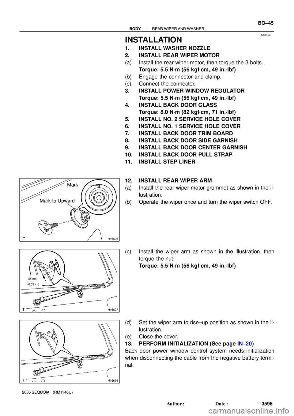
12. INSTALL REAR WIPER ARM
(a) Install the rear wiper motor grommet as shown in the il-
lustration.
(b) Operate the wiper once and turn the wiper switch OFF.
(c) Install the wiper arm as shown in the illustration, then
torque the nut.
Torque: 5.5 N´m (56 kgf´cm, 49 in.´lbf)
(d) Set the wiper arm to rise±up position as shown in the il-
lustration.
(e) Close the cover.
13. PERFORM INITIALIZATION (See page IN±20)
Back door power window control system needs initialization
when disconnecting the cable from the negative battery termi-
nal.
Page 3650 of 4323

BO4HL±02
H24383Claw
H16716
2 Clips
H16717
Clip
± BODYINSTRUMENT PANEL
BO±89
3642 Author�: Date�:
2005 SEQUOIA (RM1146U)
REMOVAL
1. DISCONNECT CABLE FROM NEGATIVE BATTERY
TERMINAL
Wait for 90 seconds after disconnecting the cable to prevent the
airbag working.
2. REMOVE FRONT DOOR SCUFF PLATE
(a) Remove the 4 screws and front door scuff plate.
(b) Use the same manner described above on the other side.
3. REMOVE COWL SIDE TRIM BOARD
(a) Remove the nut and cowl side trim board.
(b) Use the same manner described above on the other side.
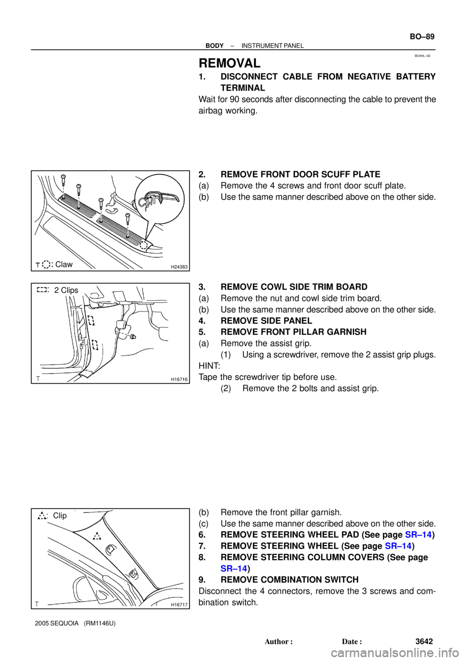
4. REMOVE SIDE PANEL
5. REMOVE FRONT PILLAR GARNISH
(a) Remove the assist grip.
(1) Using a screwdriver, remove the 2 assist grip plugs.
HINT:
Tape the screwdriver tip before use.
(2) Remove the 2 bolts and assist grip.
(b) Remove the front pillar garnish.
(c) Use the same manner described above on the other side.
6. REMOVE STEERING WHEEL PAD (See page SR±14)
7. REMOVE STEERING WHEEL (See page SR±14)
8. REMOVE STEERING COLUMN COVERS (See page
SR±14)
9. REMOVE COMBINATION SWITCH
Disconnect the 4 connectors, remove the 3 screws and com-
bination switch.
Page 3658 of 4323
BO43A±02
± BODYINSTRUMENT PANEL
BO±97
3650 Author�: Date�:
2005 SEQUOIA (RM1146U)
INSTALLATION
Installation is in the reverse order of removal (See page BO±89).
1. CONNECT CABLE TO NEGATIVE BATTERY TERMINAL
2. PERFORM INITIALIZATION (See page IN±20)
Some systems need initialization when disconnecting the cable from the negative battery terminal.
Page 3672 of 4323

BO4S7±01
± BODYFRONT SEAT (Power Adjuster Type)
BO±111
3664 Author�: Date�:
2005 SEQUOIA (RM1146U)
REMOVAL
CAUTION:
Work must not be started until at least 90 seconds after the ignition switch is turned to the LOCK posi-
tion and the negative (±) terminal cable is disconnected from the battery.
(The SRS is equipped with a back±up power source. If work is started within 90 seconds from discon-
necting the negative (±) terminal cable of the battery, the SRS may deploy.)
NOTICE:
When removing/installing and overhauling the passenger seat, check the passenger occupant clas-
sification system and perform the zero point calibration (see page DI±1128).
HINT:
The procedures listed below are for the LH side.
1. DISCONNECT CABLE FROM NEGATIVE BATTERY TERMINAL
Wait for 90 seconds after disconnecting the cable to prevent the airbag working.
2. REMOVE SEAT TRACK COVERS
Using a screwdriver, remove the seat track covers.
HINT:
Tape the screwdriver tip before use.
3. REMOVE FRONT SEAT
(a) Remove the 4 bolts.
(b) Disconnect the connectors.
(c) w/ Side airbag:
Disconnect the airbag connector.
(d) Remove the front seat.
NOTICE:
Be careful not to damage the body.
Page 3684 of 4323

BO4S9±01
± BODYFRONT SEAT (Power Adjuster Type)
BO±123
3676 Author�: Date�:
2005 SEQUOIA (RM1146U)
INSTALLATION
HINT:
The procedures listed below are for the LH side.
1. INSTALL FRONT SEAT
(a) Mount the front seat to the vehicle.
NOTICE:
Be careful not to damage the vehicle body.
(b) w/ Side airbag:
Connect the airbag connector.
(c) Connect the connectors.
(d) Slide the front seat to the rearmost position.
(e) Tighten the bolts on the front side temporarily, starting from the bolt on the inner side.
(f) Tighten them completely.
Torque: 37 N´m (380 kgf´cm, 27 ft´lbf)
(g) Slide the front seat to the foremost position.
(h) Tighten the bolts on the rear side temporarily, starting from the bolt on the inner side.
(i) Tighten them completely.
Torque: 37 N´m (380 kgf´cm, 27 ft´lbf)
2. INSTALL SEAT TRACK COVERS
3. CONNECT CABLE TO NEGATIVE BATTERY TERMINAL
4. Passenger 's seat:
PERFORM PASSENGER OCCUPANT CLASSIFICATION SYSTEM ZERO POINT CALIBRATION
(See page DI±1128)
5. PERFORM INITIALIZATION (See page IN±20)
Some systems need initialization when disconnecting the cable from the negative battery terminal.
Page 3686 of 4323

BO4SC±01
± BODYFRONT SEAT (Manual Adjuster Type)
BO±125
3678 Author�: Date�:
2005 SEQUOIA (RM1146U)
REMOVAL
CAUTION:
Work must not be started until at least 90 seconds after the ignition switch is turned to the LOCK posi-
tion and the negative (±) terminal cable is disconnected from the battery.
(The SRS is equipped with a back±up power source. If work is started within 90 seconds from discon-
necting the negative (±) terminal cable of the battery, the SRS may deploy.)
NOTICE:
When removing/installing and overhauling the passenger seat, check the passenger occupant clas-
sification system and perform the zero point calibration (see page DI±1128).
HINT:
The procedures listed below are for the LH side.
1. DISCONNECT CABLE FROM NEGATIVE BATTERY TERMINAL
Wait for 90 seconds after disconnecting the cable to prevent the airbag working.
2. REMOVE SEAT TRACK COVERS
Using a screwdriver, remove the seat track covers.
HINT:
Tape the screwdriver tip before use.
3. REMOVE FRONT SEAT
(a) Remove the 4 bolts.
(b) Disconnect the connectors.
(c) w/ Side airbag:
Disconnect the airbag connector.
(d) Remove the front seat.
NOTICE:
Be careful not to damage the vehicle body.