Page 3780 of 4323
AC3HB±02
I22634
FACE 1
FACE 2
B/L 1
B/L 2
FOOT
1
2 3 4 5
7
8
± AIR CONDITIONINGREAR A/C UNIT
AC±45
3772 Author�: Date�:
2005 SEQUOIA (RM1146U)
INSPECTION
1. INSPECT EVAPORATOR
(a) Check evaporator fins for blockage.
If the fins are clogged, clean them with compressed air.
NOTICE:
Never use water to clean the evaporator.
(b) Check fitting for cracks or scratches.
If necessary, repair or replace.
2. INSPECT HEATER RADIATOR
Inspect fins for blockage.
If the fins are clogged, clean them with compressed air.
3. INSPECT WATER VALVE SERVOMOTOR CIRCUIT
(See page DI±2361)
4. INSPECT AIR OUTLET SERVOMOTOR OPERATION
(a) Connect the positive (+) lead from the battery to terminal
7 and the negative (±) lead to terminal 8.
(b) Connect the negative (±) lead from the battery to each ter-
minal and check that the shaft rotates at each position, as
shown in the illustration.
Connected terminalPosition
1FOOT
2B/L 2
3B/L 1
4FACE 2
5FACE 1
Page 3789 of 4323

AC1KZ±05
I21361
3
3
I21362
12
AC±54
± AIR CONDITIONINGCOMPRESSOR AND MAGNETIC CLUTCH
3781 Author�: Date�:
2005 SEQUOIA (RM1146U)
COMPRESSOR AND MAGNETIC
CLUTCH
ON±VEHICLE INSPECTION
1. SET MANIFOLD GAUGE SET (See page AC±18)
2. START ENGINE
3. INSPECT COMPRESSOR FOR METALLIC SOUND
Check if a metallic sound can be heard from the compressor
when the A/C switch is on.
If a metallic sound cannot be heard, replace the compressor as-
sembly.
4. INSPECT REFRIGERANT PRESSURE
(See page AC±3)
5. STOP ENGINE
6. INSPECT VISUALLY FOR LEAKAGE OF REFRIGER-
ANT FROM SAFETY SEAL
Using a gas leak detector, check for leakage of refrigerant.
If there is any leakage, replace the compressor assembly.
7. REMOVE MANIFOLD GAUGE SET
(See page AC±19)
8. CHECK FOR LEAKAGE OF GREASE FROM CLUTCH
BEARING
9. CHECK FOR SIGNS OF OIL ON PRESSURE PLATE
If necessary, repair or replace.
10. INSPECT MAGNETIC CLUTCH BEARING FOR NOISE
(a) Start the engine.
(b) Check if abnormal noise is heard from near the compres-
sor when the A/C switch is OFF.
If abnormal noise is being emitted, replace the magnetic clutch.
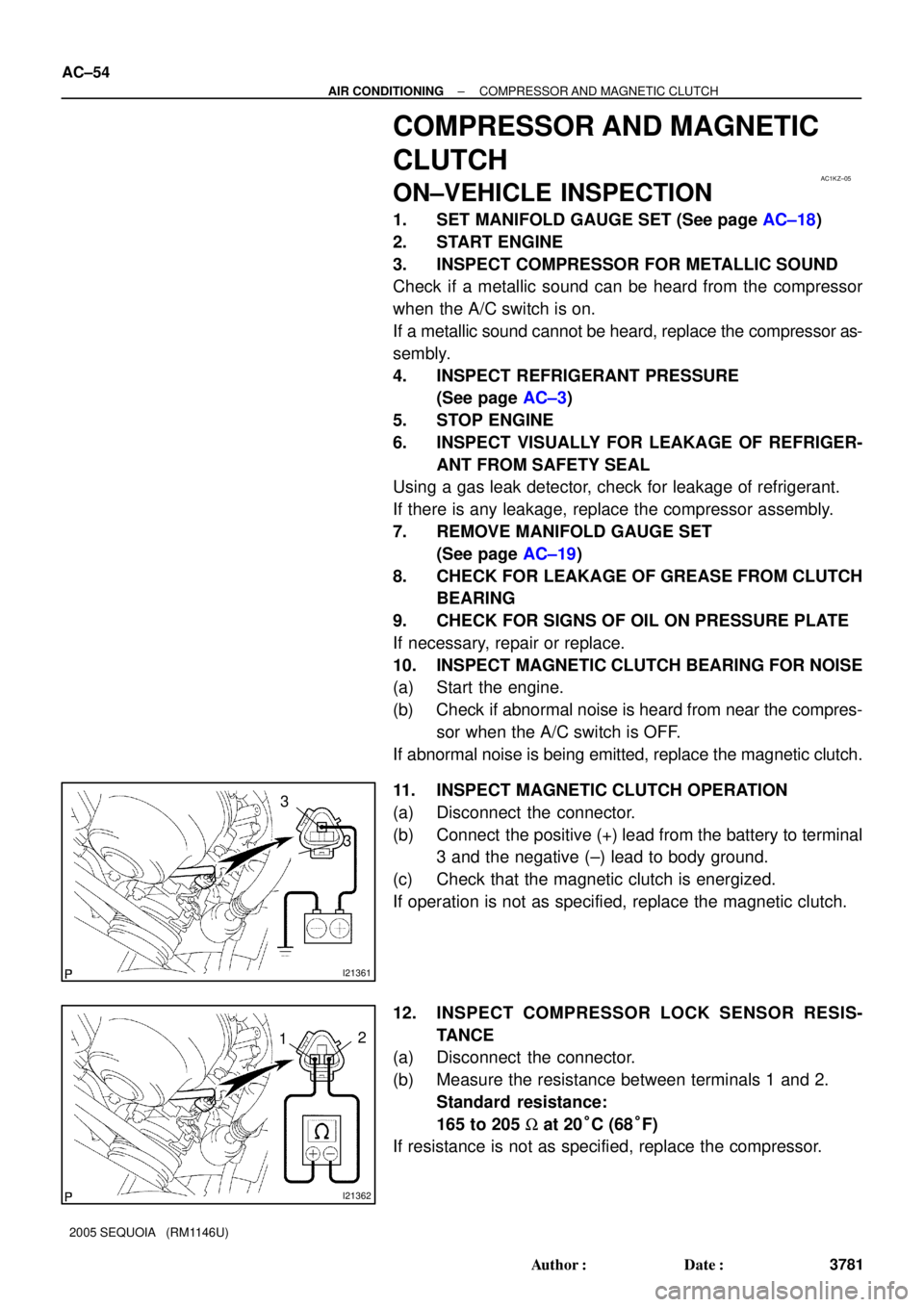
11. INSPECT MAGNETIC CLUTCH OPERATION
(a) Disconnect the connector.
(b) Connect the positive (+) lead from the battery to terminal
3 and the negative (±) lead to body ground.
(c) Check that the magnetic clutch is energized.
If operation is not as specified, replace the magnetic clutch.
12. INSPECT COMPRESSOR LOCK SENSOR RESIS-
TANCE
(a) Disconnect the connector.
(b) Measure the resistance between terminals 1 and 2.
Standard resistance:
165 to 205 W at 20°C (68°F)
If resistance is not as specified, replace the compressor.
Page 3791 of 4323
AC1L1±05
I21454
I21453
AC±56
± AIR CONDITIONINGCOMPRESSOR AND MAGNETIC CLUTCH
3783 Author�: Date�:
2005 SEQUOIA (RM1146U)
REMOVAL
1. RUN ENGINE AT IDLE SPEED WITH A/C ON FOR
APPROX. 10 MINUTES
2. STOP ENGINE
3. DISCONNECT CABLE FROM NEGATIVE BATTERY
TERMINAL
4. DISCHARGE REFRIGERANT FROM REFRIGERATION
SYSTEM
5. DISCONNECT DISCHARGE AND SUCTION HOSES
Remove the 2 nuts and disconnect both hoses.
NOTICE:
Cap the openings fitting immediately to keep moisture or
dirt out of the system.
6. REMOVE DRIVE BELT (See page AC±16)
7. REMOVE COMPRESSOR
(a) Disconnect the connector.
(b) Remove the 3 bolts and nut.
(c) Remove the cooler bracket.
(d) Remove the compressor.
Page 3795 of 4323
N04963
Dial Indicator
AC1L3±04
AC±60
± AIR CONDITIONINGCOMPRESSOR AND MAGNETIC CLUTCH
3787 Author�: Date�:
2005 SEQUOIA (RM1146U)
REASSEMBLY
Reassembly is in the reverse order of disassembly (See
page AC±57).
AFTER REASSEMBLY, CHECK MAGNETIC CLUTCH
CLEARANCE
(a) Set the dial indicator to the pressure plate of the magnetic
clutch.
(b) Connect the magnetic clutch lead wire to the positive (+)
terminal of the battery.
(c) Check the clearance between the pressure plate and ro-
tor when connecting the negative (±) terminal to the bat-
tery.
Standard clearance:
0.35 to 0.50 mm (0.014 to 0.024 in.)
If the clearance is not within the standard range, adjust the
clearance using shims to obtain the standard clearance.
Standard thickness:
0.1 mm (0.004 in.)
0.3 mm (0.012 in.)
0.5 mm (0.020in.)
Page 3796 of 4323

AC3HF±02
± AIR CONDITIONINGCOMPRESSOR AND MAGNETIC CLUTCH
AC±61
3788 Author�: Date�:
2005 SEQUOIA (RM1146U)
INSTALLATION
1. INSTALL COMPRESSOR
(a) Install the compressor with the cooler bracket with the 3 bolts and nut.
Torque:
Bolt: 47 N´m (480 kgf´cm, 35 in.´lbf)
Nut: 25 N´m (255 kgf´cm, 18 in.´lbf)
(b) Connect the connector.
2. CONNECT DISCHARGE AND SUCTION HOSES
Connect both hoses with the 2 nuts.
Torque: 10 N´m (100 kgf´cm, 7 in.´lbf)
NOTICE:
Hoses should be connected immediately after the caps have been removed.
HINT:
Lubricate 2 new O±rings with compressor oil and install them to the hoses.
3. INSTALL AND CHECK DRIVE BELT (See page AC±17, AC±15)
4. CONNECT CABLE TO NEGATIVE BATTERY TERMINAL
5. EVACUATE AIR FROM REFRIGERATION SYSTEM
6. CHARGE SYSTEM WITH REFRIGERANT
Specified amount:
Single A/C: 750 ± 50g (26.45 ± 1.76 oz.)
Dual A/C: 1050 ± 50g (37.03 ± 1.76 oz.)
7. INSPECT FOR LEAKAGE OF REFRIGERANT
Using a gas leak detector, check for leakage of refrigerant.
If there is leakage, check the tightening torque at the joints.
8. PERFORM INITIALIZATION (See page IN±20)
Some systems need initialization when disconnecting the cable from the negative battery terminal.
Page 3816 of 4323
I11143
AC3HN±02
N16762
21
± AIR CONDITIONINGBLOWER MOTOR
AC±81
3808 Author�: Date�:
2005 SEQUOIA (RM1146U)
BLOWER MOTOR
INSPECTION
1. REMOVE BLOWER MOTOR
(a) Disconnect the connector.
(b) Remove the 3 screws and motor.
2. INSPECT BLOWER MOTOR OPERATION
Connect the positive (+) lead from the battery to terminal 1 and
the negative (±) lead to terminal 2, then check that the motor op-
erates smoothly.
If operation is not as specified, replace the blower motor.
3. INSTALL BLOWER MOTOR
(a) Install the motor with the 3 screws.
(b) Connect the connector.
Page 3817 of 4323
AC3HO±02
I21378
I22633
2
1
AC±82
± AIR CONDITIONINGREAR BLOWER MOTOR
3809 Author�: Date�:
2005 SEQUOIA (RM1146U)
REAR BLOWER MOTOR
INSPECTION
1. REMOVE REAR SEAT OUTER BELT FLOOR AN-
CHORS
2. REMOVE BACK DOOR SCUFF PLATE
3. REMOVE REAR DOOR SCUFF PLATE RH
4. REMOVE REAR WINDOW SIDE GARNISH
5. REMOVE REAR QUARTER TRIM PANEL RH
6. REMOVE BLOWER MOTOR
(a) Disconnect the blower motor connector.
(b) Remove the 3 screws and blower motor.
7. INSPECT BLOWER MOTOR OPERATION
Connect the positive (+) lead from the battery to terminal 2 and
the negative (±) lead to terminal 1, then check that the motor op-
erates smoothly.
If operation is not as specified, replace the blower motor.
8. INSTALL BLOWER MOTOR
9. INSTALL REAR QUARTER TRIM PANEL RH
10. INSTALL REAR WINDOW SIDE GARNISH
11. INSTALL REAR DOOR SCUFF PLATE RH
12. INSTALL BACK DOOR SCUFF PLATE
13. INSTALL REAR SEAT OUTER BELT FLOOR AN-
CHORS
Page 3831 of 4323

AC1LZ±05
I21428
1 2
AC±96
± AIR CONDITIONINGCONDENSER FAN
3823 Author�: Date�:
2005 SEQUOIA (RM1146U)
CONDENSER FAN
ON±VEHICLE INSPECTION
1. INSPECT CONDENSER FAN OPERATION
Inspect the fan operation under the following conditions, as
shown in the chart.
Test conditions:
�Start engine
�Blower speed control switch position ºHIº
�Temperature control dial at ºCOOLº position
�Set manifold gauge set
�A/C switch ON
ConditionFan operation (Fan speed)
Refrigerant pressure is less than
1,520 kPa (15.5 kgf/cm2, 220 psi)OFF
Refrigerant pressure is 1,520 kPa
(15.5 kgf/cm2, 220 psi) or aboveRotate
If operation is not as specified, proceed to the next inspection.
2. INSPECT CONDENSER FAN MOTOR OPERATION
(a) Disconnect the fan connector.
(b) Connect the battery and ammeter.
(c) Check that the fan rotates smoothly, and then check the
reading on the ammeter.
Specified amperage: 9.2 to 11.0 A at 20°C (68°F)
If operation is not as specified, replace the fan motor.
If operation is as specified, check the pressure switch, cooling
fan relays and water temp. switch.