Page 2740 of 4323

EC0O2±01
B17527
B17528
Port APort B
Air
B17529
Port APort B
Battery Air
B17530
Port C
Port B Port A
Air
B17531
Port C
Port BPort A
Air
EC±24
± EMISSION CONTROLSECONDARY AIR INJECTION SYSTEM
2732 Author�: Date�:
2005 SEQUOIA (RM1146U)
INSPECTION
1. INSPECT AIR PUMP
(a) Connect the positive (+) lead from the battery to terminal
1 and negative (±) lead to terminal 2, and check that air
flows.
If operation is not as specified, replace the air pump.
2. INSPECT AIR SWITCHING VALVE
(a) Blow air into port A and check that air is not discharged
from port B.
(b) Apply positive battery between the terminals.
(c) Blow air into port A and check that air is discharged from
port B.
If operation is not as specified, replace the air switching valve.
3. INSPECT NO. 2 AIR SWITCHING VALVE
(a) Blow air into port B and check that air is not discharged
from port C.
(b) Apply vacuum (30 kPa (306 gf/cm
2, 4.35 psi) to port A,
blow air into port B and check that air is discharged from
port C.
If operation is not as specified, replace the No.2 air switching
valve.
Page 2743 of 4323

SF1XD±01
± SFISFI SYSTEM
SF±1
2735 Author�: Date�:
2005 SEQUOIA (RM1146U)
SFI SYSTEM
PRECAUTION
HINT:
All DTCs retained in the ECM will be erased when the negative
(±) terminal cable is removed from the battery.
If necessary, read the DTC before removing the negative (±)
terminal cable from the battery.
1. BEFORE WORKING ON FUEL SYSTEM,
DISCON-
NECT CABLE FROM NEGATIVE (±) BATTERY TERMI-
NAL
2. DO NOT SMOKE OR WORK NEAR AN OPEN FLAME
WHEN WORKING ON FUEL SYSTEM
3. KEEP GASOLINE AWAY FROM RUBBER OR
LEATH-
ER PARTS
4. MAINTENANCE PRECAUTIONS
(a) To prevent engine misfire, these precautions should be
taken.
(1) Check the battery terminals are proper connected.
(2) After repair, check that the ignition coil terminals
and all other ignition system lines are reconnected
securely.
(3) When cleaning the engine compartment, be espe-
cially careful to protect the electrical system from
water.
(b) Observe the following when handling the air fuel ratio
sensors and oxygen sensor.
(1) Do not drop the sensor or hit it against another ob-
ject.
(2) The sensor should be free from any contact with wa-
ter.
5. IF VEHICLE IS EQUIPPED WITH MOBILE RA-
DIO
SYSTEM (HAM, CB, ETC.)
If the vehicle is equipped with a mobile communication system,
refer to the precaution in the IN section.
6. AIR INDUCTION SYSTEM
(a) Removal of the engine oil dipstick, oil filler cap, PCV hose,
may break the engine.
(b) Disconnection, looseness or cracks in the parts of the air
induction system between the throttle body and cylinder
head may result in air suction and break the engine.
7. ELECTRONIC CONTROL SYSTEM
(a) Before removing SFI wiring connectors, terminals, first
disconnect the power by turning the ignition switch off or
disconnecting the negative (±) terminal cable from the
battery.
HINT:
Be sure to check DTCs before disconnecting the negative (±)
terminal cable from the battery.
Page 2744 of 4323

FI2553
SST
B16498
New Gasket
SF±2
± SFISFI SYSTEM
2736 Author�: Date�:
2005 SEQUOIA (RM1146U)
(b) When installing the battery, be especially careful to cor-
rectly connect the positive (+) and negative (±) cables.
(c) Do not give a severe impact to the SFI parts during remov-
al or installation. Handle all SFI parts carefully, especially
the ECM.
(d) Be careful during troubleshooting. Numerous transistor
circuits are used and even slight terminal contact can
cause further trouble.
(e) Do not open the ECM cover.
(f) When inspecting during rainy weather, take care to pre-
vent entry of water. Also, when washing the engine
compartment, prevent water from getting into the SFI
parts and wiring connectors.
(g) Parts should be replaced as an assembly.
(h) Care should be taken when pulling out and inserting wir-
ing connectors.
(1) Release the lock and pull out the connector, pulling
on the connectors.
(2) Fully insert the connector and check that it is locked.
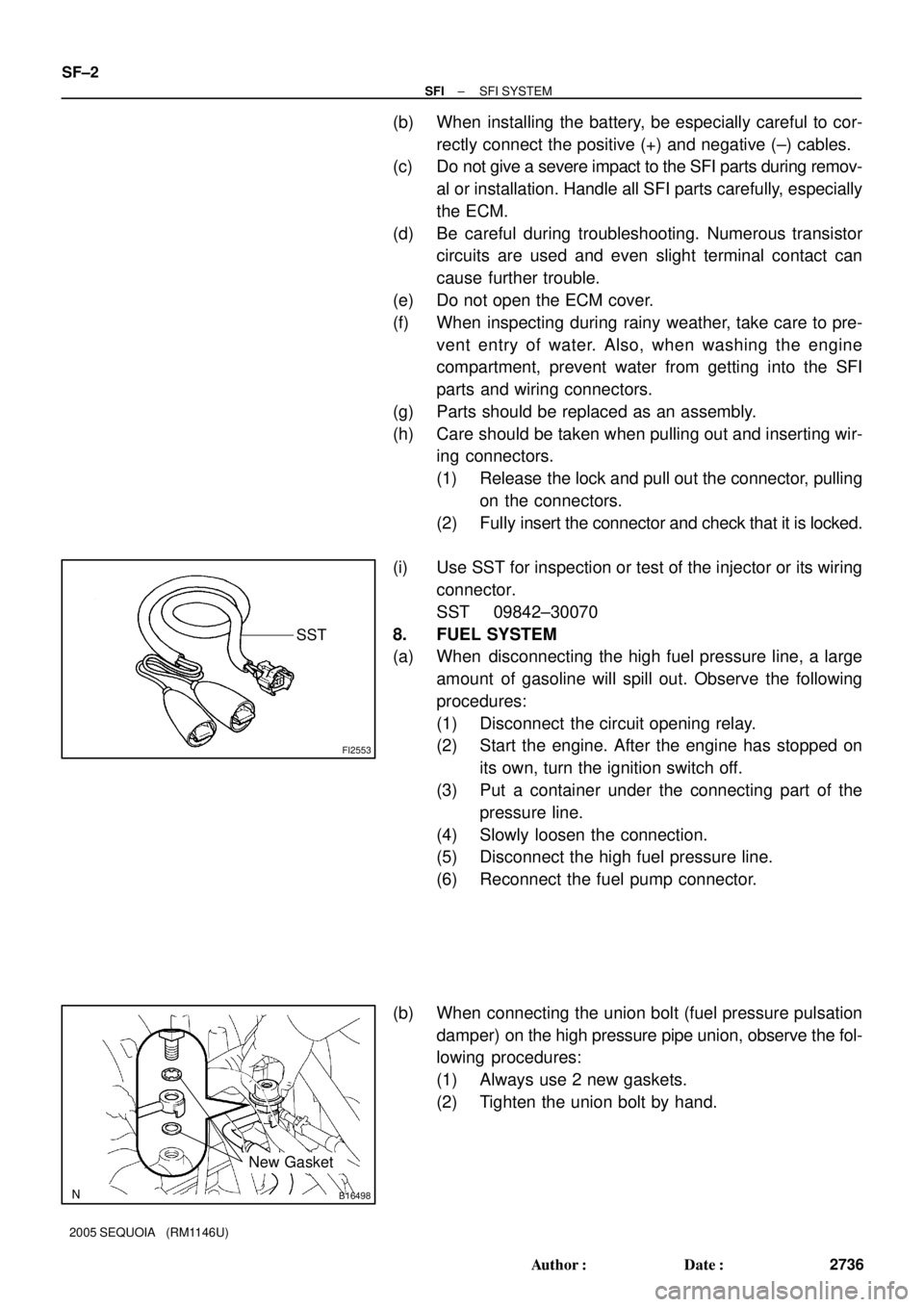
(i) Use SST for inspection or test of the injector or its wiring
connector.
SST 09842±30070
8. FUEL SYSTEM
(a) When disconnecting the high fuel pressure line, a large
amount of gasoline will spill out. Observe the following
procedures:
(1) Disconnect the circuit opening relay.
(2) Start the engine. After the engine has stopped on
its own, turn the ignition switch off.
(3) Put a container under the connecting part of the
pressure line.
(4) Slowly loosen the connection.
(5) Disconnect the high fuel pressure line.
(6) Reconnect the fuel pump connector.
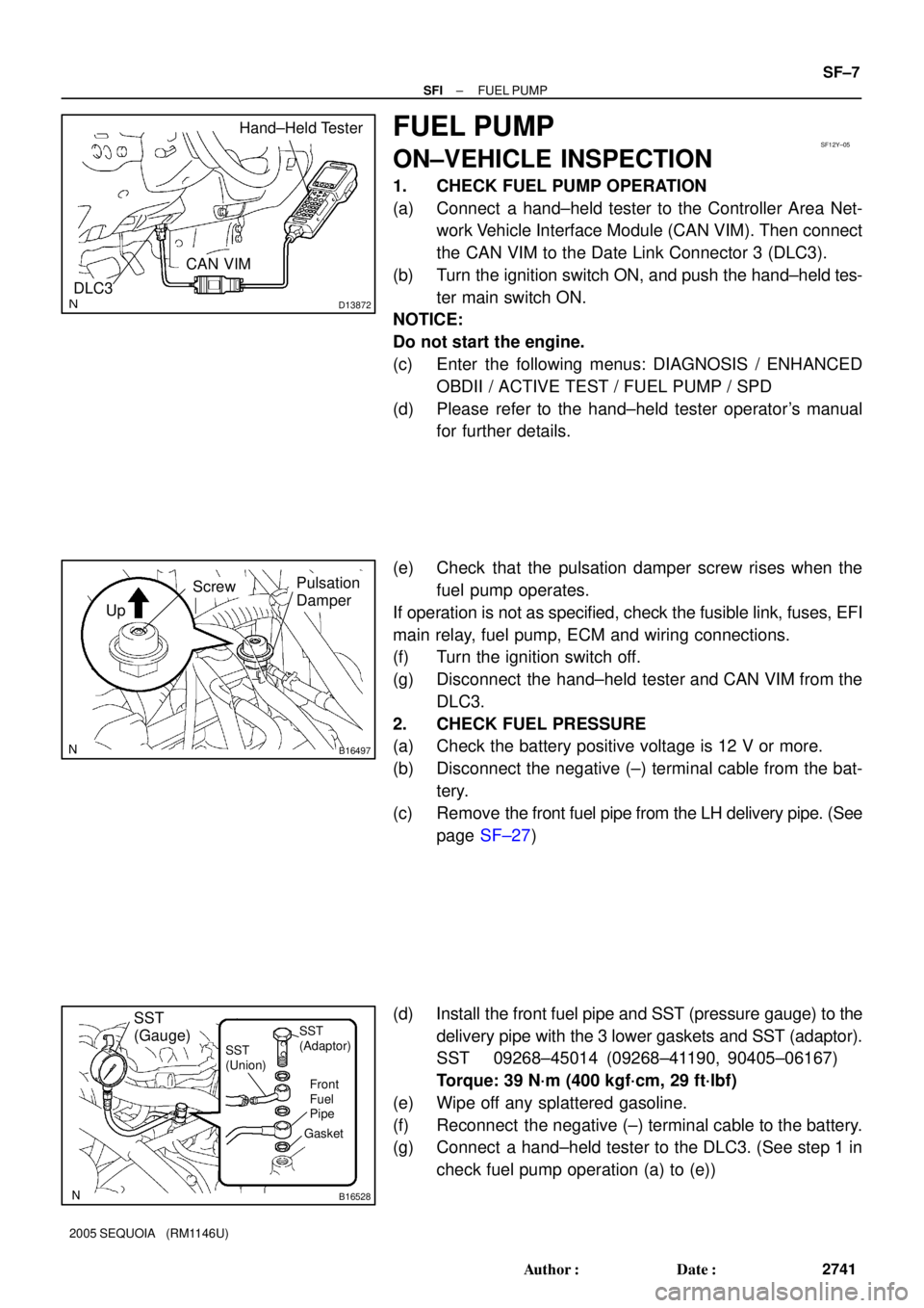
(b) When connecting the union bolt (fuel pressure pulsation
damper) on the high pressure pipe union, observe the fol-
lowing procedures:
(1) Always use 2 new gaskets.
(2) Tighten the union bolt by hand.
Page 2749 of 4323

D13872
Hand±Held Tester
DLC3
CAN VIM
SF12Y±05
B16497
Up
Pulsation
DamperScrew
B16528
SST
(Gauge)
Front
Fuel
Pipe
Gasket SST
(Union)SST
(Adaptor)
± SFIFUEL PUMP
SF±7
2741 Author�: Date�:
2005 SEQUOIA (RM1146U)
FUEL PUMP
ON±VEHICLE INSPECTION
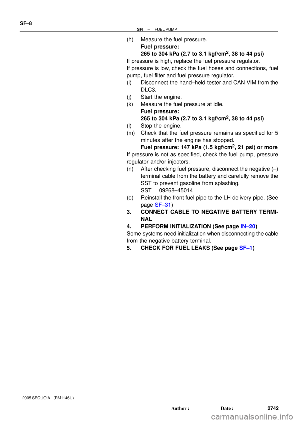
1. CHECK FUEL PUMP OPERATION
(a) Connect a hand±held tester to the Controller Area Net-
work Vehicle Interface Module (CAN VIM). Then connect
the CAN VIM to the Date Link Connector 3 (DLC3).
(b) Turn the ignition switch ON, and push the hand±held tes-
ter main switch ON.
NOTICE:
Do not start the engine.
(c) Enter the following menus: DIAGNOSIS / ENHANCED
OBDII / ACTIVE TEST / FUEL PUMP / SPD
(d) Please refer to the hand±held tester operator's manual
for further details.
(e) Check that the pulsation damper screw rises when the
fuel pump operates.
If operation is not as specified, check the fusible link, fuses, EFI
main relay, fuel pump, ECM and wiring connections.
(f) Turn the ignition switch off.
(g) Disconnect the hand±held tester and CAN VIM from the
DLC3.
2. CHECK FUEL PRESSURE
(a) Check the battery positive voltage is 12 V or more.
(b) Disconnect the negative (±) terminal cable from the bat-
tery.
(c) Remove the front fuel pipe from the LH delivery pipe. (See
page SF±27)
(d) Install the front fuel pipe and SST (pressure gauge) to the
delivery pipe with the 3 lower gaskets and SST (adaptor).
SST 09268±45014 (09268±41190, 90405±06167)
Torque: 39 N´m (400 kgf´cm, 29 ft´lbf)
(e) Wipe off any splattered gasoline.
(f) Reconnect the negative (±) terminal cable to the battery.
(g) Connect a hand±held tester to the DLC3. (See step 1 in
check fuel pump operation (a) to (e))
Page 2750 of 4323

SF±8
± SFIFUEL PUMP
2742 Author�: Date�:
2005 SEQUOIA (RM1146U)
(h) Measure the fuel pressure.
Fuel pressure:
265 to 304 kPa (2.7 to 3.1 kgf/cm
2, 38 to 44 psi)
If pressure is high, replace the fuel pressure regulator.
If pressure is low, check the fuel hoses and connections, fuel
pump, fuel filter and fuel pressure regulator.
(i) Disconnect the hand±held tester and CAN VIM from the
DLC3.
(j) Start the engine.
(k) Measure the fuel pressure at idle.
Fuel pressure:
265 to 304 kPa (2.7 to 3.1 kgf/cm
2, 38 to 44 psi)
(l) Stop the engine.
(m) Check that the fuel pressure remains as specified for 5
minutes after the engine has stopped.
Fuel pressure: 147 kPa (1.5 kgf/cm
2, 21 psi) or more
If pressure is not as specified, check the fuel pump, pressure
regulator and/or injectors.
(n) After checking fuel pressure, disconnect the negative (±)
terminal cable from the battery and carefully remove the
SST to prevent gasoline from splashing.
SST 09268±45014
(o) Reinstall the front fuel pipe to the LH delivery pipe. (See
page SF±31)
3. CONNECT CABLE TO NEGATIVE BATTERY TERMI-
NAL
4. PERFORM INITIALIZATION (See page IN±20)
Some systems need initialization when disconnecting the cable
from the negative battery terminal.
5. CHECK FOR FUEL LEAKS (See page SF±1)
Page 2757 of 4323
B17610
Ohmmeter
SF131±03
B17611Battery 1 2
± SFIFUEL PUMP
SF±15
2749 Author�: Date�:
2005 SEQUOIA (RM1146U)
INSPECTION
1. INSPECT FUEL PUMP RESISTANCE
Using an ohmmeter, measure the resistance between the ter-
minals.
Resistance: 0.2 to 3.0 W at 20°C (68°F)
If the resistance is not as specified, replace the fuel pump.
2. INSPECT FUEL PUMP OPERATION
(a) Connect the lead wire to the fuel pump.
(b) Connect the positive (+) lead from the battery to terminal
1 of the connector, and the negative (±) lead to terminal
2. Check that the fuel pump operates.
NOTICE:
�These tests must be done quickly (within 10 seconds)
to prevent the coil from burning out.
�Keep the fuel pump as far away from the battery as
possible.
�Always do switching on the battery side.
If operation is not as specified, replace the fuel pump and/or
read wire.
(c) Disconnect the lead wire to the fuel pump.
Page 2771 of 4323

SF134±04
B07326
SST
InjectorSST
SST
SST
Pressure Regulator
B04988
Pressure Regulator
SST (Hose)
SST (Union)
Fuel Return Hose
B00884
SST
(Adaptor)
SST
(Hose)
SST
(Clamp)
Vinyl
HoseO±Ring
D13872
Hand±Held Tester
DLC3
CAN VIM
± SFIINJECTOR
SF±29
2763 Author�: Date�:
2005 SEQUOIA (RM1146U)
INSPECTION
1. INSPECT INJECTOR INJECTION
CAUTION:
Keep the injector clean of sparks during the test.
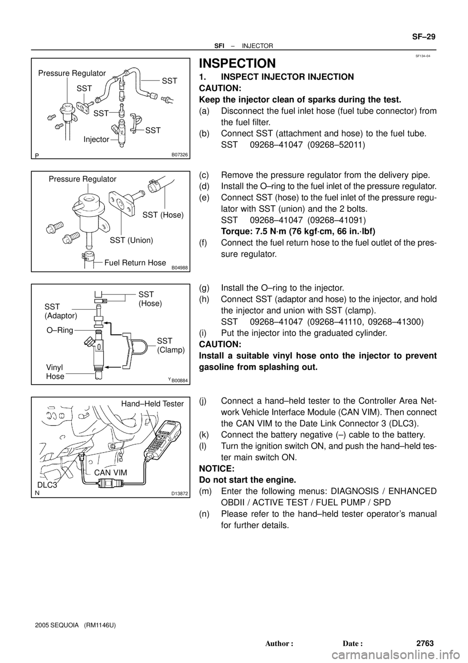
(a) Disconnect the fuel inlet hose (fuel tube connector) from
the fuel filter.
(b) Connect SST (attachment and hose) to the fuel tube.
SST 09268±41047 (09268±52011)
(c) Remove the pressure regulator from the delivery pipe.
(d) Install the O±ring to the fuel inlet of the pressure regulator.
(e) Connect SST (hose) to the fuel inlet of the pressure regu-
lator with SST (union) and the 2 bolts.
SST 09268±41047 (09268±41091)
Torque: 7.5 N´m (76 kgf´cm, 66 in.´lbf)
(f) Connect the fuel return hose to the fuel outlet of the pres-
sure regulator.
(g) Install the O±ring to the injector.
(h) Connect SST (adaptor and hose) to the injector, and hold
the injector and union with SST (clamp).
SST 09268±41047 (09268±41110, 09268±41300)
(i) Put the injector into the graduated cylinder.
CAUTION:
Install a suitable vinyl hose onto the injector to prevent
gasoline from splashing out.
(j) Connect a hand±held tester to the Controller Area Net-
work Vehicle Interface Module (CAN VIM). Then connect
the CAN VIM to the Date Link Connector 3 (DLC3).
(k) Connect the battery negative (±) cable to the battery.
(l) Turn the ignition switch ON, and push the hand±held tes-
ter main switch ON.
NOTICE:
Do not start the engine.
(m) Enter the following menus: DIAGNOSIS / ENHANCED
OBDII / ACTIVE TEST / FUEL PUMP / SPD
(n) Please refer to the hand±held tester operator's manual
for further details.
Page 2772 of 4323
B00883
ConnectSST
(Wire)
A01293
SF±30
± SFIINJECTOR
2764 Author�: Date�:
2005 SEQUOIA (RM1146U)
(o) Connect SST (wire) to the injector and battery for 15 se-
conds, and measure the injection volume with a gra-
duated cylinder. Test each injector 2 or 3 times.
SST 09842±30070
Volume: 56 to 69 cm
3 (3.4 to 4.2 cu in.) per 15 seconds
Difference between each injector:
13 cm
3 (0.8 cu in.) or less
If the injection volume is not as specified, replace the injector.
2. INSPECT LEAKAGE
(a) Under the above conditions, disconnect the tester probes
of SST (wire) from the battery and check fuel leakage
from the injector.
SST 09842±30070
Fuel drop: 1 drop or less per 12 minutes
(b) Turn the ignition switch off.
(c) Disconnect the negative (±) terminal cable from the bat-
tery.
(d) Remove the SST and fuel tube connector.
SST 09268±41047, 09842±30070
(e) Disconnect the hand±held tester and CAN VIM from the
DLC3.
(f) Reconnect the fuel inlet pipe to the fuel tube.