Page 2571 of 4323
I28847
GNDI19 Integration Control and Panel:ACC
I22574
Instrument Panel J/B
CIG Fuse
± DIAGNOSTICSAIR CONDITIONING SYSTEM
DI±2369
2563 Author�: Date�:
2005 SEQUOIA (RM1146U)
INSPECTION PROCEDURE
1 Check voltage between terminals ACC and GND of integration control and panel.
PREPARATION:
Remove the integration control and panel with connectors still
connected.
CHECK:
(a) Turn the ignition switch to ACC.
(b) Measure the voltage between terminals ACC and GND of
the integration control and panel.
OK:
Voltage : 10 to 14 V
OK Proceed to next circuit inspection shown in
problem symptoms table (See page DI±2304).
NG
2 Check CIG fuse.
PREPARATION:
Remove the CIG fuse from the cowl side J/B.
CHECK:
Check continuity of the CIG fuse.
OK:
Continuity
NG Check for short in all the harness and compo-
nents connected to the CIG fuse (See attached
wiring diagram).
OK
Check and repair harness and connector between integration control and panel and battery.
Page 2577 of 4323
I07839
21
± DIAGNOSTICSAIR CONDITIONING SYSTEM
DI±2375
2569 Author�: Date�:
2005 SEQUOIA (RM1146U)
INSPECTION PROCEDURE
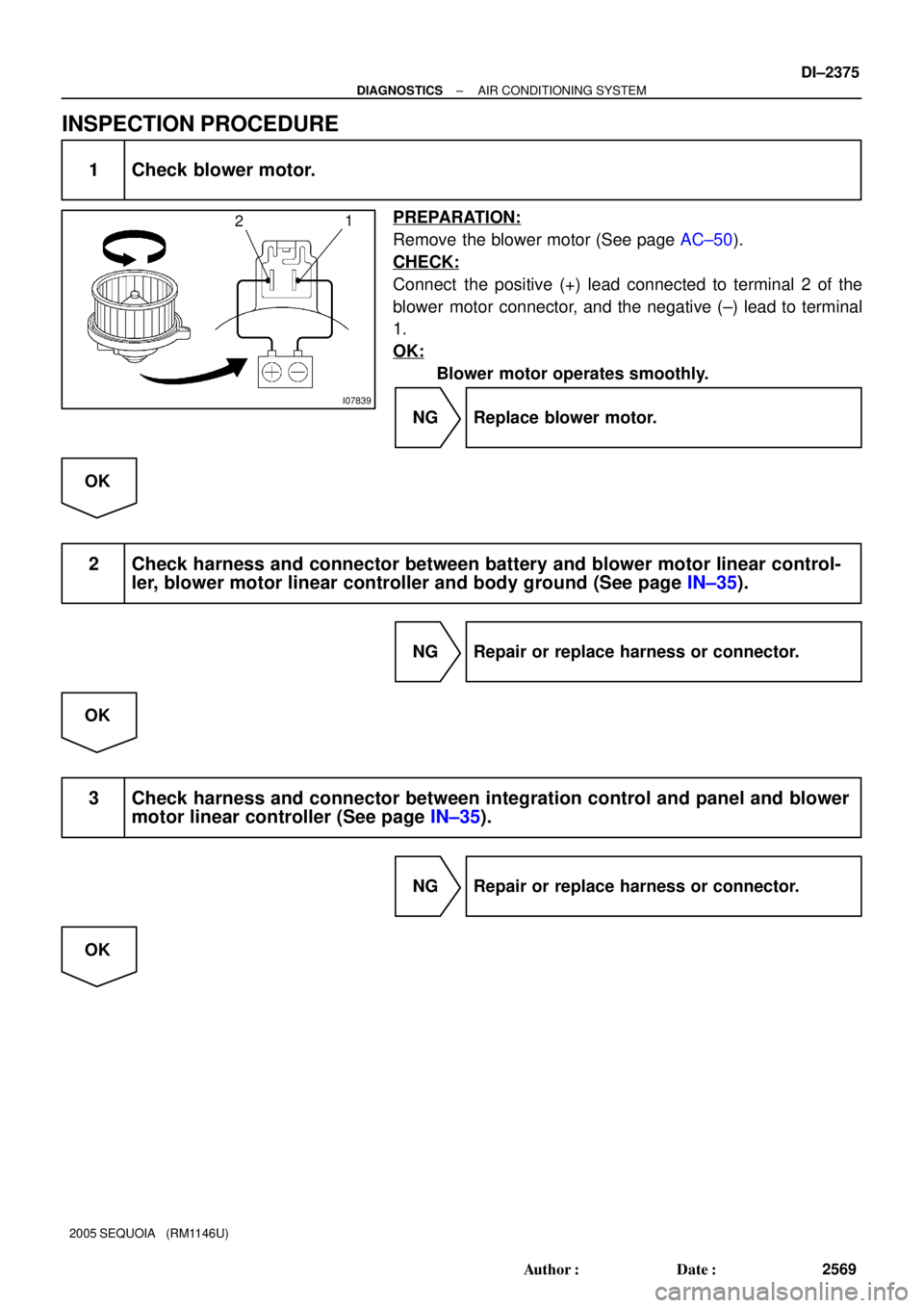
1 Check blower motor.
PREPARATION:
Remove the blower motor (See page AC±50).
CHECK:
Connect the positive (+) lead connected to terminal 2 of the
blower motor connector, and the negative (±) lead to terminal
1.
OK:
Blower motor operates smoothly.
NG Replace blower motor.
OK
2 Check harness and connector between battery and blower motor linear control-
ler, blower motor linear controller and body ground (See page IN±35).
NG Repair or replace harness or connector.
OK
3 Check harness and connector between integration control and panel and blower
motor linear controller (See page IN±35).
NG Repair or replace harness or connector.
OK
Page 2580 of 4323
I28847
RrBLWI21 Integration Control and Panel:
I24460
DI±2378
± DIAGNOSTICSAIR CONDITIONING SYSTEM
2572 Author�: Date�:
2005 SEQUOIA (RM1146U)
INSPECTION PROCEDURE
1 Check voltage between terminal RrBLW of integration control and panel and
body ground.
PREPARATION:
Remove the integration control and panel with connectors still
connected.
CHECK:
(a) Turn the ignition switch to ON.
(b) Operate the blower motor.
(c) Measure the voltage between terminal RrBLW of the in-
tegration control and panel and body ground.
OK:
Voltage: 1 to 3 V
OK Go to step 3.
NG
2 Check blower motor.
PREPARATION:
Remove the blower motor.
CHECK:
Connect the positive (+) lead from the battery to terminal 2 and
the negative (±) lead to terminal 1 of the blower motor connec-
tor.
OK:
Blower motor operates smoothly.
NG Replace blower motor.
OK
Page 2582 of 4323
I07763
1
2
4
I07764
3
4
DI±2380
± DIAGNOSTICSAIR CONDITIONING SYSTEM
2574 Author�: Date�:
2005 SEQUOIA (RM1146U)
4 Check power transistor.
PREPARATION:
Remove the power transistor (See page AC±84).
CHECK:
(a) Connect the positive (+) lead from the battery to terminal
1 through a 12 V ± 3.4 W test bulb and the negative (±)
lead to terminal 2.
(b) Check the test bulb lights up when another positive (+)
lead is connected to terminal 4 through a 12 V ± 3.4 W test
bulb.
OK:
Test bulb lights up.
CHECK:
Measure the resistance between terminals 3 and 4.
OK:
Resistance: 2.0 to 2.4 kW
NG Replace power transistor.
OK
5 Check harness and connector between integration control and panel and power
transistor, power transistor and body ground (See page IN±35).
NG Repair or replace harness or connector.
OK
Replace integration control and panel.
Page 2586 of 4323
Z18060
15 2
3
12 3 5
I21361
3
DI±2384
± DIAGNOSTICSAIR CONDITIONING SYSTEM
2578 Author�: Date�:
2005 SEQUOIA (RM1146U)
5 Check magnetic clutch relay.
PREPARATION:
Remove the magnetic clutch relay from the engine room J/B.
CHECK:
Measure the resistance according to the value(s) in the table
below.
OK:
Tester connectionConditionSpecified condition
3 ± 5Always10 kW or higher
3 ± 5
Voltage is applied
between terminals
1 and 2Below 1W (Battery
voltage is applied between
terminals 1 and 2)
NG Replace magnetic clutch relay.
OK
6 Check A/C magnetic clutch.
PREPARATION:
Disconnect the magnetic clutch connector.
CHECK:
Connect the positive (+) battery lead to the magnetic clutch con-
nector terminal 3.
OK:
Magnetic clutch is energized.
NG Replace A/C magnetic clutch.
OK
7 Check harness and connector between integration control and panel (MGC ter-
minal) and body ground (See page IN±35).
NG Repair or replace harness or connector.
OK
Replace integration control and panel.
Page 2590 of 4323

COMPRESSION
INSPECTION
HINT:
If there is lack of power, excessive oil consumption")
EM0KR±10
A04458
Compression
Gauge
± ENGINE MECHANICALCOMPRESSION
EM±3
2582 Author�: Date�:
2005 SEQUOIA (RM1146U)
COMPRESSION
INSPECTION
HINT:
If there is lack of power, excessive oil consumption or poor fuel
economy, measure the compression pressure.
1. WARM UP AND STOP ENGINE
Allow the engine to warm up to normal operating temperature.
2. REMOVE SPARK PLUGS (See page IG±1)
3. CHECK CYLINDER COMPRESSION PRESSURE
(a) Insert a compression gauge into the spark plug hole.
(b) Fully open the throttle.
(c) While cranking the engine, measure the compression
pressure.
HINT:
Always use a fully charged battery to obtain engine speed of
250 rpm or more.
(d) Repeat steps (a) through (c) for each cylinder.
NOTICE:
This measurement must be done in as short a time as pos-
sible.
Compression pressure:
1,373 kPa (14.0 kgf/cm
2, 199 psi) or more
Minimum pressure:
1,030 kPa (10.5 kgf/cm
2, 149 psi)
Difference between each cylinder:
98 kPa (1.0 kgf/cm
2, 14 psi) or less
(e) If the cylinder compression in one or more cylinders is low,
pour small amount of engine oil into the cylinder through
the spark plug hole and repeat steps (a) through (c) for
cylinders with low compression.
�If adding oil helps the compression, chances are
that the piston rings and/or cylinder bore are worn
or damaged.
�If pressure stays low, a valve may be sticking or
seating is improper, or there may be leakage past
the gasket.
4. REINSTALL SPARK PLUGS (See page IG±1)
Page 2591 of 4323

VALVE CLEARANCE
INSPECTION
HINT:
Inspect and adjust the valve clearance when the engine")
EM0KS±09
A23300
A23301
EM±4
± ENGINE MECHANICALVALVE CLEARANCE
2583 Author�: Date�:
2005 SEQUOIA (RM1146U)
VALVE CLEARANCE
INSPECTION
HINT:
Inspect and adjust the valve clearance when the engine is cold.
1. REMOVE BATTERY CLAMP COVER
2. REMOVE THROTTLE BODY COVER
3. REMOVE AIR CLEANER AND INTAKE AIR CONNEC-
TOR ASSEMBLY
4. REMOVE NO.3 TIMING BELT COVERS
(See page EM±16)
5. REMOVE IGNITION COILS (See page IG±5)
6. REMOVE RH CYLINDER HEAD COVER
Remove the 9 bolts, seal washers and cylinder head cover.
7. REMOVE LH CYLINDER HEAD COVER
(a) Remove the oil dipstick for the transmission.
(b) Disconnect the PCV hose.
(c) Disconnect the engine wire clamp from the wire bracket
on the cylinder head cover.
(d) Remove the 9 bolts, 9 seal washers and cylinder head
cover.
8. SET NO.1 CYLINDER TO TDC/COMPRESSION
(a) Turn the crankshaft pulley, and align its groove with timing
mark º0º of the No.1 timing belt cover.
(b) Check that the timing marks of the camshaft timing pul-
leys and timing belt rear plates are aligned.
If not, turn the crankshaft 1 revolution (360°) and align the mark
as above.
Page 2593 of 4323

10. ADJUST VALVE CLEARANCE
(a) Remove the timing belt. (See page EM±16)
(b) Remove the camshafts. (See p")
A02213
EM±6
± ENGINE MECHANICALVALVE CLEARANCE
2585 Author�: Date�:
2005 SEQUOIA (RM1146U)
10. ADJUST VALVE CLEARANCE
(a) Remove the timing belt. (See page EM±16)
(b) Remove the camshafts. (See page EM±36)
(c) Remove the valve lifter and adjusting shim.
(d) Determine the replacement adjusting shim size according
to these Formula or Charts:
(1) Using a micrometer, measure the thickness of the
removed shim.
(2) Calculate the thickness of a new shim so that the
valve clearance comes within the specified value.
T ........... Thickness of removed shim
A ........... Measured valve clearance
N ........... Thickness of new shim
Intake: N = T + (A ± 0.20 mm (0.008 in.))
Exhaust: N = T + (A ± 0.30 mm (0.012 in.))
(3) Select a new shim with thickness as close as pos-
sible to the calculated value.
HINT:
Shims are available in 41 increments of 0.020 mm (0.0008 in.),
from 2.00 mm (0.0787 in.) to 2.80 mm (0.1102 in.).
(e) Place a new adjusting shim on the valve.
(f) Place the valve lifter.
(g) Reinstall the camshafts. (See page EM±60)
(h) Reinstall the timing belt. (See page EM±23)
(i) Recheck the valve clearance.
11. REINSTALL CYLINDER HEAD COVERS
12. REINSTALL IGNITION COILS
13. REINSTALL NO.3 TIMING BELT COVERS
(See page EM±23)
14. REINSTALL AIR CLEANER AND INTAKE AIR
CONNECTOR ASSEMBLY
15. REINSTALL THROTTLE BODY COVER
16. REINSTALL BATTERY CLAMP COVER