Page 2823 of 4323
SF0Q1±12
± SFIENGINE CONTROL MODULE (ECM)
SF±81
2815 Author�: Date�:
2005 SEQUOIA (RM1146U)
INSPECTION
1. DISCONNECT CABLE FROM NEGATIVE (±) BATTERY TERMINAL
2. REMOVE REMOVE GLOVE COMPARTMENT
(a) Remove the 2 screws and glove compartment door.
(b) Remove the 3 screws and lower No.2 finish panel.
3. REMOVE HEATER TO REGISTER DUCT
4. REMOVE ECM
(a) Disconnect the 5 connectors.
(b) Remove the 2 bolts and ECM.
5. INSPECT ECM (See page DI±34)
6. REINSTALL ECM
(a) Install the ECM with the 2 bolts.
(b) Connect the 5 connectors.
7. INSTALL HEATER TO REGISTER DUCT
8. INSTALL GLOVE COMPARTMENT
(a) Install the lower No.2 finish panel with 3 screws.
(b) Install the glove compartment door with the 2 screws.
9. CONNECT CABLE TO NEGATIVE (±) BATTERY TERMINAL
10. PERFORM INITIALIZATION (See page IN±20)
Some system need initialzation when disconnecting the cable from the battery terminal.
Page 2871 of 4323
")
SPARK TEST
Replace the crankshaft position sensor.
CHECK CONNECTION OF IGNITION COIL
CONNECTOR
CHECK RESISTANCE OF CRANKSHAFT POSITION
Resistance:Cold Hot
CHECK IGT SIGNAL FROM ECM
(See page DI±221)
REPAIR WIRING BETWEEN IGNITION COIL
AND ECM
Connect securely.
Check wiring between ignition switch
to ignition coil (with igniter).
Check ECM (See page IN±35)
NG
OK
OK
OKBAD
BAD
BAD
CHANGE IT TO NORMAL IGNITION COIL (WITH
IGNITER) AND PERFORM SPARK TEST AGAIN
OKReplace the ignition coil (with igniter).
NO
OK
985 ± 1,600 W1,265 ± 1,890 WBAD
CHECK POWER SUPPLY TO IGNITION COIL (WITH
1. Turn ignition switch to ON.
2. Check that there is battery voltage at ignition coil positive (+)
terminal.IGNITER)
CHECK TDC
NG
SENSOR (See page IG±12)
B03198
16 mm Plug Wrench
IG±2
± IGNITIONIGNITION SYSTEM
2863 Author�: Date�:
2005 SEQUOIA (RM1146U)
If the spark does not occur, do the test as follows:
(7) Using a 16 mm plug wrench, install the spark plugs.
Torque: 17.5 N´m (180 kgf´cm, 13 ft´lbf)
(8) Reinstall the ignition coils (with igniter).
(see page IG±6)
2. INSPECT SPARK PLUGS
(a) Remove the ignition coils (with igniter).
(see page IG±5)
(b) Using a 16 mm plug wrench, remove the spark plugs.
Page 2887 of 4323
ST08Z±07
B04548
B04549
Starter
Connector
Engine Wire Protector
± STARTINGSTARTER
ST±5
2879 Author�: Date�:
2005 SEQUOIA (RM1146U)
REMOVAL
1. REMOVE THROTTLE BODY COVER
2. REMOVE INTAKE AIR CONNECTOR
3. DISCONNECT CABLE FROM NEGATIVE (±) BATTERY
TERMINAL
4. DISCONNECT THROTTLE BODY ASSEMBLY FROM
INTAKE MANIFOLD (See page SF±42)
5. REMOVE INTAKE MANIFOLD ASSEMBLY
(See page EM±36)
6. REMOVE AIR PUMP ASSEMBLY (See page EC±22)
7. REMOVE STARTER
(a) Remove the 2 bolts holding the starter from the cylinder
block.
(b) Disconnect the starter from the cylinder block.
(c) Disconnect the starter connector.
(d) Remove the nut, bolt and disconnect the starter wire.
(e) Remove the bolt, and disconnect the engine wire protec-
tor from the starter.
(f) Remove the starter.
Page 2897 of 4323

ST094±06
B02289
Terminal 50
Battery Terminal C
B02290
Battery Terminal CDisconnect
B02291
Disconnect
Battery
B02292
Terminal 30
Battery Ammeter Terminal 50
± STARTINGSTARTER
ST±15
2889 Author�: Date�:
2005 SEQUOIA (RM1146U)
TEST
NOTICE:
These tests must be done within 3 to 5 seconds to avoid the
coil to be burned ± out.
1. DO PULL±IN TEST
(a) Disconnect the field coil lead wire from terminal C.
(b) Connect the battery to the magnetic switch as shown.
Check that the pinion gear moves outward.
2. DO HOLDING TEST
While connected as above with the pinion gear out, disconnect
the negative (±) lead from terminal C. Check that the pinion gear
remains out.
3. INSPECT CLUTCH PINION GEAR RETURN
Disconnect the negative (±) lead from the starter body. Check
that the pinion gear returns inward.
4. DO NO±LOAD PERFORMANCE TEST
(a) Connect the battery and ammeter to the starter as shown.
(b) Check that the starter rotates smoothly and steadily with
the pinion gear moving out. Check that the ammeter
shows the specified current.
Specified current:
At 11.5 V: 100 A or less
Page 2898 of 4323
ST095±06
B04549
Starter
Connector
Engine Wire Protector
B04548
ST±16
± STARTINGSTARTER
2890 Author�: Date�:
2005 SEQUOIA (RM1146U)
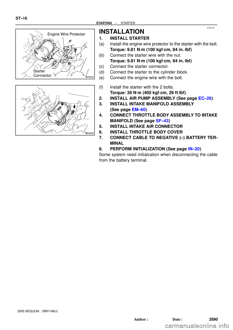
INSTALLATION
1. INSTALL STARTER
(a) Install the engine wire protector to the starter with the bolt.
Torque: 9.81 N´m (100 kgf´cm, 84 in.´lbf)
(b) Connect the starter wire with the nut.
Torque: 9.81 N´m (100 kgf´cm, 84 in.´lbf)
(c) Connect the starter connector.
(d) Connect the starter to the cylinder block.
(e) Connect the engine wire with the bolt.
(f) Install the starter with the 2 bolts.
Torque: 39 N´m (400 kgf´cm, 29 ft´lbf)
2. INSTALL AIR PUMP ASSEMBLY (See page EC±26)
3. INSTALL INTAKE MANIFOLD ASSEMBLY
(See page EM±60)
4. CONNECT THROTTLE BODY ASSEMBLY TO INTAKE
MANIFOLD (See page SF±43)
5. INSTALL INTAKE AIR CONNECTOR
6. INSTALL THROTTLE BODY COVER
7. CONNECT CABLE TO NEGATIVE (±) BATTERY TER-
MINAL
8. PERFORM INITIALIZATION (See page IN±20)
Some system need initialzation when disconnecting the cable
from the battery terminal.
Page 2899 of 4323
ST0PJ±01
A00968
Continuity
No continuity12
5
3 OhmmeterOhmmeter
A00969
Ohmmeter
Battery 1
2
5
3
Continuity
± STARTINGSTARTER RELAY
ST±17
2891 Author�: Date�:
2005 SEQUOIA (RM1146U)
STARTER RELAY
INSPECTION
1. REMOVE STARTER RELAY
Remove the relay box cover and starter relay.
2. INSPECT STARTER RELAY CONTINUITY
(a) Using an ohmmeter, check that there is continuity be-
tween terminals 1 and 2.
If there is no continuity, replace the relay.
(b) Check that there is no continuity between terminals 3 and
5.
If there is continuity, replace the relay.
3. INSPECT STARTER RELAY OPERATION
(a) Apply battery positive voltage across terminals 1 and 2.
(b) Using an ohmmeter, check that there is continuity be-
tween terminals 3 and 5.
If there is no continuity, replace the relay.
4. REINSTALL STARTER RELAY
Page 2900 of 4323

ST0OT±02
S04972ContinuityNo continuity 12
5
3 Ohmmeter
Ohmmeter Continuity
4
S04971
OhmmeterBattery12
5
3
ContinuityOhmmeter
No Continuity4 ST±18
± STARTINGACC CUT RELAY
2892 Author�: Date�:
2005 SEQUOIA (RM1146U)
ACC CUT RELAY
INSPECTION
1. REMOVE ACC CUT RELAY
Remove the cowl side trim board LH and ACC cut relay.
2. INSPECT ACC CUT RELAY CONTINUITY
(a) Using an ohmmeter, check that there is continuity be-
tween terminals 1 and 2.
If there is no continuity, replace the relay.
(b) Check that there is no continuity between terminals 3 and
5.
If there is continuity, replace the relay.
(c) Check that there is continuity between terminals 3 and 4.
If there is no continuity, replace the relay.
3. INSPECT ACC CUT RELAY OPERATION
(a) Apply battery positive voltage across terminals 1 and 2.
(b) Using an ohmmeter, check that there is no continuity be-
tween terminals 3 and 4.
If there is continuity, replace the relay.
(c) Using an ohmmeter, check that there is continuity be-
tween terminals 3 and 5.
If there is no continuity, replace the relay.
4. REINSTALL ACC CUT RELAY
Page 2901 of 4323

CHARGING SYSTEM
ON±VEHICLE INSPECTION
C")
CH0K7±03
B07241
Upper Level
Lower Level
B07242
Except Maintenance±Free Battery
± CHARGINGCHARGING SYSTEM
CH±1
2893 Author�: Date�:
2005 SEQUOIA (RM1146U)
CHARGING SYSTEM
ON±VEHICLE INSPECTION
CAUTION:
�Check that the battery cables are connected to the
correct terminals.
�Disconnect the battery cables when the battery is giv-
en a quick charge.
�Do not perform tests with a high voltage insulation re-
sistance tester.
�Never disconnect the battery while the engine is run-
ning.
1. CHECK BATTERY ELECTROLYTE LEVEL
Check the electrolyte quantity of each cell.
If under the lower level, replace the battery (or add distilled wa-
ter if possible) and check the charging system.
2. Except Maintenance±Free Battery:
CHECK BATTERY SPECIFIC GRAVITY
Check the specific gravity of each cell.
Standard specific gravity:
1.25 to 1.29 at 20°C (68°F)
If the specific gravity is less than the specification, charge the
battery.
3. Maintenance±Free Battery:
CHECK BATTERY VOLTAGE
(a) In the case that 20 minutes have not passe4d after stop-
ping the engine, turn on the ignition switch and the electri-
cal system (headlight, blower motor, rear defogger, etc.)
for 60 seconds before removing the surface charge.
(b) Turn the ignition switch OFF and turn off the electrical sys-
tems.