Page 2902 of 4323

B07243
Voltmeter
Maintenance±Free Battery
P14937
Maintenance±Free Battery
GREEN EYE DARK EYECLEAR EYE or
CHARGED DISCHARGED ADD WATERLIGHT YELLOW
Z00030
B00807
CH±2
± CHARGINGCHARGING SYSTEM
2894 Author�: Date�:
2005 SEQUOIA (RM1146U)
(c) Measure the battery voltage between the negative (±)
and positive (+) terminals of the battery.
Standard voltage:
12.5 to 12.9 V at 20°C (68°F)
If the voltage is less than the specification, charge the battery.
HINT:
Check the indicator as shown in the illustration.
4. CHECK BATTERY TERMINALS, FUSIBLE LINK AND
FUSES
(a) Check that the battery terminals are not loose or cor-
roded.
(b) Check the fusible link and fuses for continuity.
5. INSPECT DRIVE BELT
HINT:
Since the belt tensioner is used, checking the belt tension is not
necessary.
(a) Visually check the drive belt for excessive wear, frayed
cords etc.
If necessary, replace the drive belt.
HINT:
�Cracks on the rib side of a drive belt are considered ac-
ceptable. If the drive belt has chunks missing from the
ribs, it should be replaced.
�The drive belt tension can be released by turning the belt
tensioner counterclockwise. The pulley bolt for the belt
tensioner has a left±hand thread.
(b) Check the belt tensioner operation.
�Check that the belt tensioner moves downward
when the drive belt is pressed down at the points in-
dicated in the illustration with approx. 98 N (10 kgf,
22.0 lbf) of force.
�Check the alignment of the belt tensioner pulley to
make sure the drive belt does not slipped off the
pulley.
If necessary, replace the belt tensioner.
Page 2903 of 4323

�Check that t")
B00808
B
A
AC2024
CORRECT WRONG
Z03473
Ammeter
Disconnect Wire
from Terminal B
Battery
VoltmeterB
Generator
± CHARGINGCHARGING SYSTEM
CH±3
2895 Author�: Date�:
2005 SEQUOIA (RM1146U)
�Check that the arrow mark on the belt tensioner falls
within area A of the scale.
If it is outside area A, replace the drive belt.
HINT:
�When a new belt is installed, it should lie within area B. If
not, the drive belt is not correct.
�After installing a belt, check that it fits properly in the
ribbed grooves.
�Check by hand to confirm that the belt does not slipped
out of the groove on the bottom of the pulley.
6. REMOVE ENGINE UNDER COVER NO.1
7. VISUALLY CHECK GENERATOR WIRING AND LIS-
TEN FOR ABNORMAL NOISES
(a) Check that the wiring is in good condition.
(b) Check that there is no abnormal noise from the generator
while the engine is running.
8. CHECK CHARGE WARNING LIGHT CIRCUIT
(a) Warm up the engine and then turn it off.
(b) Switch off all accessories.
(c) Turn the ignition switch ON, and check that the charge
warning light comes on.
(d) Start the engine, and check that the light goes off.
If the light does not go off as specified, troubleshoot the charge
light circuit.
9. INSPECT CHARGING CIRCUIT WITHOUT LOAD
HINT:
If a battery/generator tester is available, connect the tester to
the charging circuit as per manufacturer's instructions.
(a) If a tester is not available, connect a voltmeter and amme-
ter to the charging circuit as follows:
�Disconnect the wire from terminal B of the genera-
tor, and connect it to the negative (±) tester probe
of the ammeter.
�Connect the positive (+) tester probe of the amme-
ter to terminal B of the generator.
�Connect the positive (+) tester probe of the voltme-
ter to terminal B of the generator.
�Ground the negative (±) tester probe of the voltme-
ter.
(b) Check the charging circuit as follows:
With the engine running from idling to 2,000 rpm, check
the reading on the ammeter and voltmeter.
Standard amperage: 10 A or less
Standard voltage: 13.2 to 14.0 V
Page 2904 of 4323
CH±4
± CHARGINGCHARGING SYSTEM
2896 Author�: Date�:
2005 SEQUOIA (RM1146U)
If the voltmeter reading is more than the standard voltage, re-
place the voltage regulator.
If the voltmeter reading is less than the standard voltage, check
the voltage regulator and generator.
10. INSPECT CHARGING CIRCUIT WITH LOAD
(a) With the engine running at 2,000 rpm, turn on the high
beam headlights and set the heater blower switch to HI.
(b) Check the reading on the ammeter.
Standard amperage: 30 A or more
If the ammeter reading is less than the standard amperage, re-
pair the generator.
HINT:
If the battery is fully charged, the indication will sometimes be
less than standard amperage.
11. REINSTALL ENGINE UNDER COVER
Page 2907 of 4323
CH0LY±02
B00809
± CHARGINGGENERATOR
CH±7
2899 Author�: Date�:
2005 SEQUOIA (RM1146U)
REMOVAL
1. REMOVE ENGINE UNDER COVER
2. REMOVE THROTTLE BODY COVER
3. DISCONNECT CABLE FROM NEGATIVE (±) BATTERY
TERMINAL
4. DISCONNECT INTAKE AIR CONNECTOR FROM
THROTTLE BODY
5. REMOVE DRIVE BELT
Loosen the belt tension by turning the belt tensioner counter-
clockwise, and remove the drive belt.
HINT:
The pulley bolt for the belt tensioner has a left hand thread.
6. REMOVE PS VANE PUMP FROM ENGINE
(See page SR±28)
7. REMOVE GENERATOR
(a) Disconnect the generator connector.
(b) Remove the terminal cap and nut, and disconnect the
generator wire.
(c) Disconnect the wire clamp from the cord clip on the gener-
ator.
(d) Remove the bolt, the 2 nuts and the generator.
Page 2916 of 4323

INSTALLATION
1. INSTALL GENERATOR
(a) Install the generator with the bolt and the 2 nuts.
Torque:
Bolt: 39 N")
CH0M3±02
B00809
CH±16
± CHARGINGGENERATOR
2908 Author�: Date�:
2005 SEQUOIA (RM1146U)
INSTALLATION
1. INSTALL GENERATOR
(a) Install the generator with the bolt and the 2 nuts.
Torque:
Bolt: 39 N´m (400 kgf´cm, 29 ft´lbf)
Nut 10 mm: 39 N´m (400 kgf´cm, 29 ft´lbf)
Nut 8 mm: 15.5 N´m (158 kgf´cm, 11 ft´lbf)
(b) Connect the generator connector.
(c) Connect the generator wire with the nut.
Torque: 9.8 N´m (100 kgf´cm, 87 in.´lbf)
(d) Install the terminal cap.
(e) Install the wire clamp to the cord clip on the generator.
2. INSTALL PS VANE PUMP (See page SR±36)
3. INSTALL DRIVE BELT
Install the belt by turning the belt tensioner counterclockwise.
HINT:
The pulley bolt for the belt tensioner has a left ± hand thread.
4. CONNECT INTAKE AIR CONNECTOR TO THROTTLE
BODY
5. PERFORM ON±VEHICLE INSPECTION
(See page CH±1)
6. INSTALL THROTTLE BODY COVER
7. INSTALL ENGINE UNDER COVER
8. CONNECT CABLE TO NEGATIVE (±) BATTERY TER-
MINAL
9. PERFORM INITIALIZATION (See page IN±20)
Some system need initialzation when disconnecting the cable
from the battery terminal.
Page 2917 of 4323
AT130±01
± AUTOMATIC TRANSMISSION (A750E, A750F)AUTOMATIC TRANSMISSION SYSTEM
AT±1
2909 Author�: Date�:
2005 SEQUOIA (RM1146U)
AUTOMATIC TRANSMISSION SYSTEM
PRECAUTION
NOTICE:
When disconnecting the battery terminal, initialize the following system after the terminal is recon-
nected.
System NameSee Page
Back Door Power Window Control SystemBE±77
Page 2947 of 4323
TR04G±02
± TRANSFERTRANSFER SYSTEM
TR±1
2939 Author�: Date�:
2005 SEQUOIA (RM1146U)
TRANSFER SYSTEM
PRECAUTION
NOTICE:
When disconnecting the battery terminal, initialize the following system after the terminal is recon-
nected.
System NameSee Page
Back Door Power Window Control SystemBE±77
When working with FIPG material, you must observe the following:
�Using a razor blade and gasket scraper, remove all the old FIPG material from gasket surfaces.
�Thoroughly clean all components to remove any loose material.
�Clean both sealing surfaces with a non±residue solvent.
�Apply FIPG in an approx. 1.2 mm (0.047 in.) wide bead along the sealing surface.
�Parts must be assembled within 10 minutes of FIPG application. Otherwise, the FIPG material
must be removed and reapplied.
Page 3017 of 4323
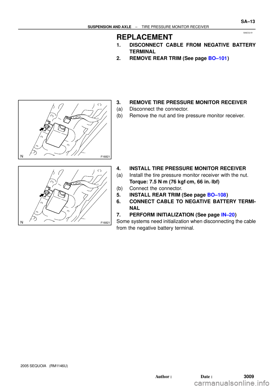
SA2CQ±01
F16821
F16821
± SUSPENSION AND AXLETIRE PRESSURE MONITOR RECEIVER
SA±13
3009 Author�: Date�:
2005 SEQUOIA (RM1146U)
REPLACEMENT
1. DISCONNECT CABLE FROM NEGATIVE BATTERY
TERMINAL
2. REMOVE REAR TRIM (See page BO±101)
3. REMOVE TIRE PRESSURE MONITOR RECEIVER
(a) Disconnect the connector.
(b) Remove the nut and tire pressure monitor receiver.
4. INSTALL TIRE PRESSURE MONITOR RECEIVER
(a) Install the tire pressure monitor receiver with the nut.
Torque: 7.5 NVm (76 kgfVcm, 66 in.Vlbf)
(b) Connect the connector.
5. INSTALL REAR TRIM (See page BO±108)
6. CONNECT CABLE TO NEGATIVE BATTERY TERMI-
NAL
7. PERFORM INITIALIZATION (See page IN±20)
Some systems need initialization when disconnecting the cable
from the negative battery terminal.