Page 3019 of 4323
SA2CS±01
F19828
F19829
Lithium battery
Terminal
± SUSPENSION AND AXLETIRE PRESSURE MONITOR VALVE
SA±15
3011 Author�: Date�:
2005 SEQUOIA (RM1146U)
DISPOSAL
HINT:
The tire pressure monitor valve sub±assy is powered by a lithi-
um battery. When disposing of the tire pressure monitor valve
sub±assy, remove the battery and dispose of it correctly.
DISPOSE OF TIRE PRESSURE MONITOR VALVE
(a) Insert the tip of a screwdriver into the clearance and pry
off the cover. Remove the back cover.
(b) The battery and base board covered with silicone resin
are exposed. While taking out the battery, cut off the 2 ter-
minals which connect the battery and base board.
Page 3024 of 4323
SA2CV±01
F16822
F16822
SA±20
± SUSPENSION AND AXLETIRE PRESSURE MONITOR ECU
3016 Author�: Date�:
2005 SEQUOIA (RM1146U)
REPLACEMENT
1. DISCONNECT CABLE FROM NEGATIVE BATTERY
TERMINAL
2. REMOVE INTEGRATION CONTROL PANEL
(See page BO±89)
3. REMOVE GLOVE COMPARTMENT
(See page BO±89)
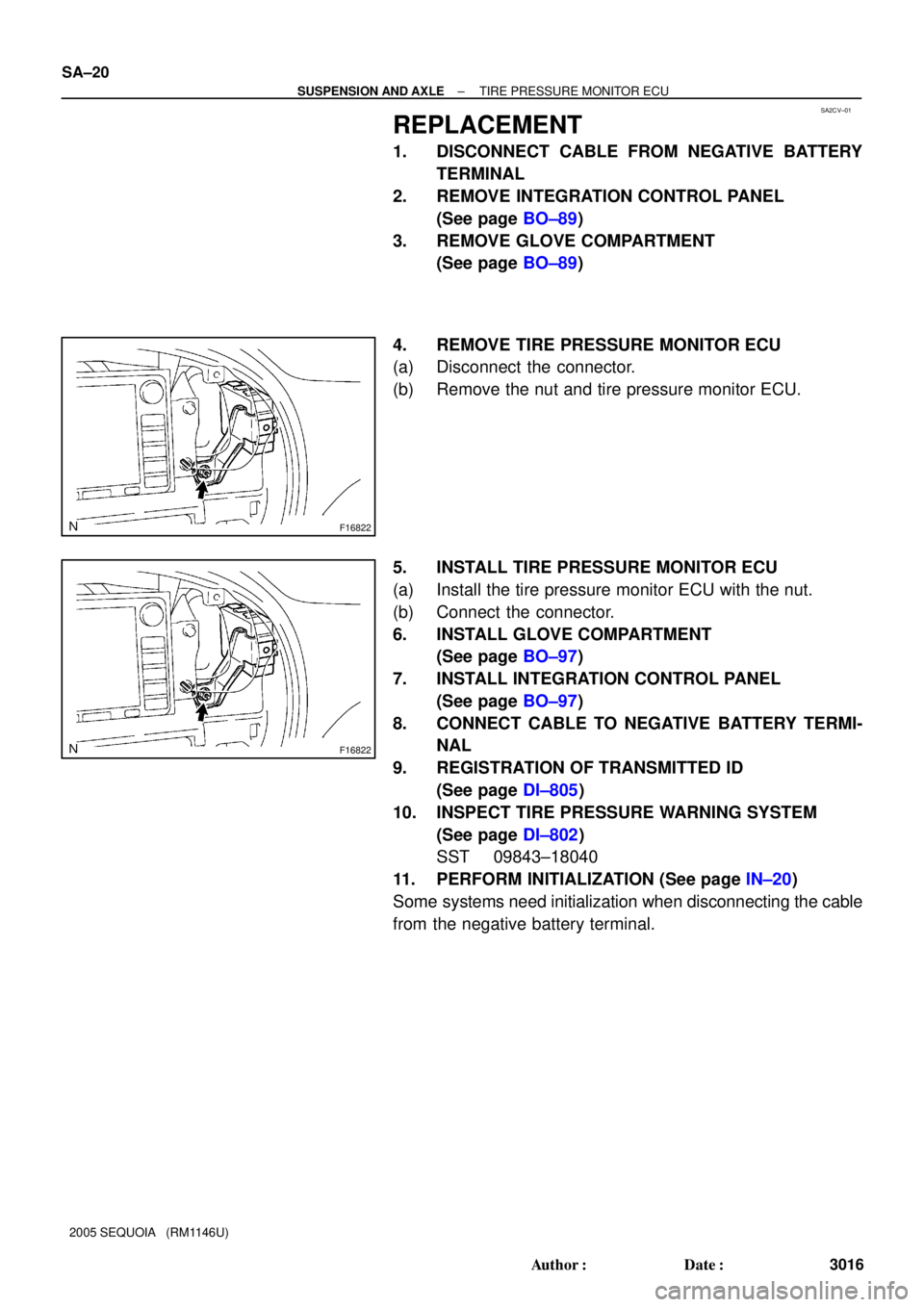
4. REMOVE TIRE PRESSURE MONITOR ECU
(a) Disconnect the connector.
(b) Remove the nut and tire pressure monitor ECU.
5. INSTALL TIRE PRESSURE MONITOR ECU
(a) Install the tire pressure monitor ECU with the nut.
(b) Connect the connector.
6. INSTALL GLOVE COMPARTMENT
(See page BO±97)
7. INSTALL INTEGRATION CONTROL PANEL
(See page BO±97)
8. CONNECT CABLE TO NEGATIVE BATTERY TERMI-
NAL
9. REGISTRATION OF TRANSMITTED ID
(See page DI±805)
10. INSPECT TIRE PRESSURE WARNING SYSTEM
(See page DI±802)
SST 09843±18040
11. PERFORM INITIALIZATION (See page IN±20)
Some systems need initialization when disconnecting the cable
from the negative battery terminal.
Page 3065 of 4323

INSPECTION
1. INSPECT A.D.D. ACTUATOR
(a)")
SA23Q±03
F06635
Actuator side:
1423 56
F19317
2WD/4HI Switch
± SUSPENSION AND AXLEA.D.D. CONTROL SYSTEM
SA±61
3057 Author�: Date�:
2005 SEQUOIA (RM1146U)
INSPECTION
1. INSPECT A.D.D. ACTUATOR
(a) Disconnect the actuator connector.
(b) Measure the resistance between terminals 2 and 6.
Standard resistance: 0.3 ± 100 W
(c) Measure the resistance between terminal 2 or 6 and body
ground.
Standard resistance: More than 0.5 MW
If the resistance value is not as specified, replace the actuator
assembly.
2. INSPECT A.D.D. ACTUATOR OPERATION
Apply battery positive voltage between terminals 2 and 6, and
check the actuator operation by sound, A.D.D. status and conti-
nuity between terminals 3 and 4.
Battery voltage
applied terminal3 ± 4 terminals continuityA.D.D.
status
2 (+) ± 6 (±)ContinuityConnected
2 (±) ± 6 (+)No continuityDisconnected
If the operation is not as specified, replace the actuator assem-
bly.
3. INSPECT LIMIT SWITCH CONTINUITY
(a) Connect the actuator connector.
(b) Push the 2WD/4HI switch and check that the 4WD indica-
tor light comes on after it is blinking.
(c) Check the A.D.D. actuator operation by sound.
(d) Disconnect the actuator connector.
(e) Check the continuity between each terminal, as shown in
the chart.
Tester connected terminal numberSpecified condition
1 ± 3No continuity
1 ± 4No continuity
3 ± 5Continuity
4 ± 5No continuity
(f) Connect the actuator connector.
Page 3175 of 4323
SA2CW±01
F16828
F16828
± SUSPENSION AND AXLESUSPENSION CONTROL ECU
SA±171
3167 Author�: Date�:
2005 SEQUOIA (RM1146U)
SUSPENSION CONTROL ECU
REPLACEMENT
1. DISCONNECT CABLE FROM NEGATIVE BATTERY
TERMINAL
2. REMOVE INTEGRATION CONTROL PANEL
(See page BO±89)
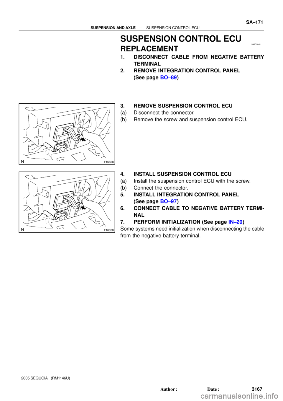
3. REMOVE SUSPENSION CONTROL ECU
(a) Disconnect the connector.
(b) Remove the screw and suspension control ECU.
4. INSTALL SUSPENSION CONTROL ECU
(a) Install the suspension control ECU with the screw.
(b) Connect the connector.
5. INSTALL INTEGRATION CONTROL PANEL
(See page BO±97)
6. CONNECT CABLE TO NEGATIVE BATTERY TERMI-
NAL
7. PERFORM INITIALIZATION (See page IN±20)
Some systems need initialization when disconnecting the cable
from the negative battery terminal.
Page 3236 of 4323

STEERING SYSTEM
PRECAUTION
�Care must be taken to replace parts properly because they could affect the performa")
SR01S±06
± STEERINGSTEERING SYSTEM
SR±1
3228 Author�: Date�:
2005 SEQUOIA (RM1146U)
STEERING SYSTEM
PRECAUTION
�Care must be taken to replace parts properly because they could affect the performance of the
steering system and result in a driving hazard.
�The SEQUOIA is equipped with an SRS (Supplemental Restraint System) such as the driver air-
bag and front passenger airbag. Failure to carry out service operation in the correct sequence
could cause the SRS to unexpectedly deploy during servicing, possibly leading to a serious
accident. Before servicing (including removal or installation of parts, inspection or replace-
ment), be sure to read the notices precautionary in the RS section.
�When disconnecting the battery terminal, initialize the following system after the terminal is re-
connected.
System NameSee Page
Back Door Power Window Control SystemBE±77
�When replacing the steering angle sensor, drive the vehicle straight ahead at a speed of 6.5 mph
(10.5 km/h) or more. Accordingly, zero point calibration of the steering angle sensor is per-
formed.
�After performing ºFront wheel alignment adjustmentº, clearing and reading the yaw rate & de-
celeration sensor zero point calibration data is necessary (See page DI±897).
Page 3249 of 4323

REMOVAL
1. DIS")
SR1KD±01
F17124
Screw CaseTorx® Screw
F17904
Correct
Wrong
Airbag Connectors
F06699
Matchmarks
SST
SR±14
± STEERINGTILT STEERING COLUMN
3241 Author�: Date�:
2005 SEQUOIA (RM1146U)
REMOVAL
1. DISCONNECT CABLE FROM NEGATIVE BATTERY
TERMINAL
Wait for 90 seconds after disconnecting the cable to prevent the
airbag working.
2. REMOVE STEERING WHEEL PAD
NOTICE:
If the airbag connector is disconnected with the ignition
switch in the ACC or ON position, DTCs will be recorded.
(a) Place the front wheels facing straight ahead.
(b) Remove the steering wheel lower No. 3 cover.
(c) Remove the steering wheel lower No. 2 cover.
(d) Using a torx® socket wrench (T30), loosen the 2 torx®
screws.
HINT:
Loosen each screw until the groove along the screw circumfer-
ence is caught on the screw case.
(e) Pull out the wheel pad from the steering wheel.
(f) Using a screwdriver, disconnect the airbag connectors.
CAUTION:
�When storing the steering wheel pad, keep the upper
surface of the pad facing upward.
�Never disassemble the steering wheel pad.
NOTICE:
When removing the steering wheel pad, take care not to
pull the airbag wire harness.
(g) Disconnect the horn terminal and remove the steering
wheel pad.
3. REMOVE STEERING WHEEL
(a) Remove the steering wheel set nut.
(b) Put matchmarks on the steering wheel and main shaft as-
sembly.
(c) Using SST, remove the wheel.
SST 09950±50013 (09951±05010, 09952±05010,
09953±05020, 09954±05021)
4. REMOVE UPPER AND LOWER COLUMN COVERS
Remove the 3 screws, upper and lower column covers.
Page 3260 of 4323

15. INSTALL STEERING WHEEL
(a) Align the matchmark on the wheel with the one on the")
F17129
Torx® Screw
Screw Case
± STEERINGTILT STEERING COLUMN
SR±25
3252 Author�: Date�:
2005 SEQUOIA (RM1146U)
15. INSTALL STEERING WHEEL
(a) Align the matchmark on the wheel with the one on the
main shaft.
(b) Install the wheel set nut.
Torque: 50 N´m (510 kgf´cm, 37 ft´lbf)
16. INSTALL STEERING WHEEL PAD
NOTICE:
�Never use airbag parts from another vehicle. When
replacing parts, replace with new ones.
�Make sure that the wheel pad is installed with the spe-
cified torque.
�If the wheel pad has been dropped, or there are
cracks, dents or other defects on the case or connec-
tor, replace the wheel pad with a new one.
�When installing the wheel pad, take care that the wir-
ings do not interfere with other parts and are not
pinched between other parts.
(a) Connect the horn terminal.
(b) Connect the airbag connectors.
(c) Install the wheel pad after confirming that the circumfer-
ence groove of the torx® screw is caught on the screw
case.
(d) Using a torx® socket wrench (T30), tighten the 2 torx®
screws.
Torque: 8.8 N´m (90 kgf´cm, 78 in.´lbf)
(e) Install the steering wheel lower No. 2 cover.
(f) Install the steering wheel lower No. 3 cover.
17. CHECK STEERING WHEEL CENTER POINT
18. CONNECT CABLE TO NEGATIVE BATTERY TERMI-
NAL
19. PERFORM INITIALIZATION (See page IN±20)
Some systems need initialization when disconnecting the cable
from the negative battery terminal.
Page 3275 of 4323
SR02O±09
F13616SST
SR±40
± STEERINGPOWER STEERING GEAR
3267 Author�: Date�:
2005 SEQUOIA (RM1146U)
REMOVAL
NOTICE:
Remove the steering wheel assembly before the steering
gear removal, because there is possibility of breaking of
the spiral cable.
1. DISCONNECT CABLE FROM NEGATIVE BATTERY
TERMINAL
Wait for 90 seconds after disconnecting the cable to prevent the
airbag working.
2. PLACE FRONT WHEELS FACING STRAIGHT AHEAD
3. REMOVE STEERING WHEEL PAD
(See page SR±14)
4. REMOVE STEERING WHEEL (See page SR±14)
5. DISCONNECT RH AND LH TIE ROD ENDS
(See page SA±86)
6. DISCONNECT NO. 2 INTERMEDIATE SHAFT AS-
SEMBLY (See page SR±14)
7. DISCONNECT CLAMP PLATE
Remove the bolt and disconnect the clamp plate.
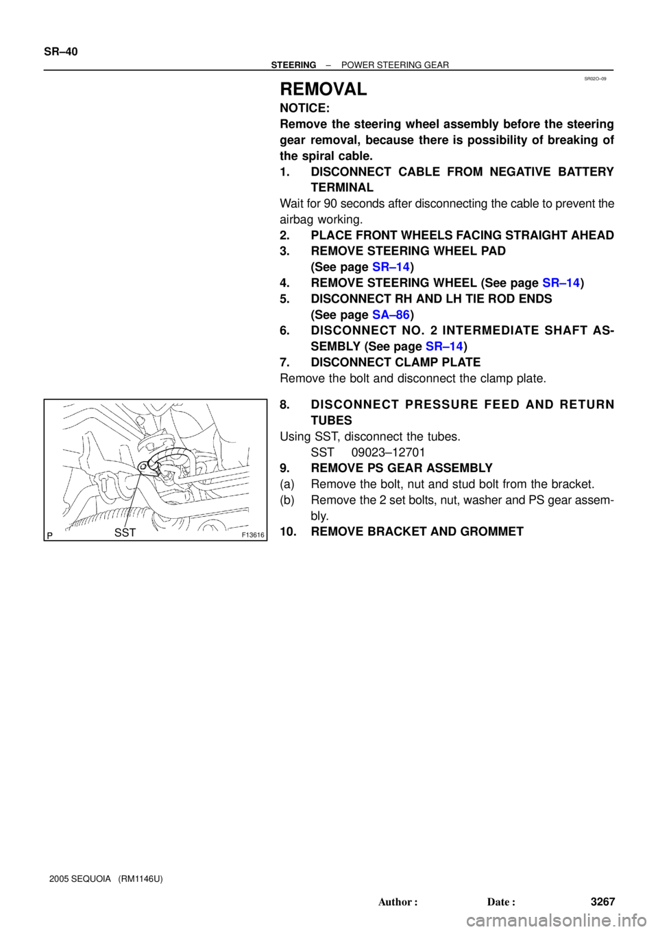
8. DISCONNECT PRESSURE FEED AND RETURN
TUBES
Using SST, disconnect the tubes.
SST 09023±12701
9. REMOVE PS GEAR ASSEMBLY
(a) Remove the bolt, nut and stud bolt from the bracket.
(b) Remove the 2 set bolts, nut, washer and PS gear assem-
bly.
10. REMOVE BRACKET AND GROMMET