Page 2468 of 4323

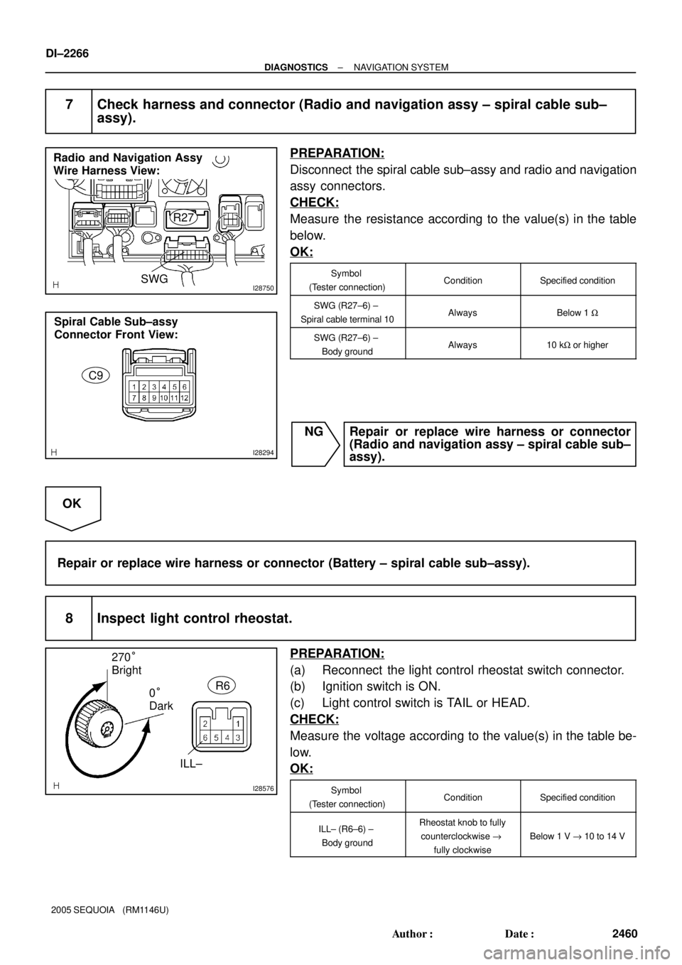
I28750
Radio and Navigation Assy
Wire Harness View:
R27
SWG
I28294
Spiral Cable Sub±assy
Connector Front View:
C9
I28576
270°
Bright
0°
DarkR6
ILL±
DI±2266
± DIAGNOSTICSNAVIGATION SYSTEM
2460 Author�: Date�:
2005 SEQUOIA (RM1146U)
7 Check harness and connector (Radio and navigation assy ± spiral cable sub±
assy).
PREPARATION:
Disconnect the spiral cable sub±assy and radio and navigation
assy connectors.
CHECK:
Measure the resistance according to the value(s) in the table
below.
OK:
Symbol
(Tester connection)ConditionSpecified condition
SWG (R27±6) ±
Spiral cable terminal 10AlwaysBelow 1 W
SWG (R27±6) ±
Body groundAlways10 kW or higher
NG Repair or replace wire harness or connector
(Radio and navigation assy ± spiral cable sub±
assy).
OK
Repair or replace wire harness or connector (Battery ± spiral cable sub±assy).
8 Inspect light control rheostat.
PREPARATION:
(a) Reconnect the light control rheostat switch connector.
(b) Ignition switch is ON.
(c) Light control switch is TAIL or HEAD.
CHECK:
Measure the voltage according to the value(s) in the table be-
low.
OK:
Symbol
(Tester connection)ConditionSpecified condition
ILL± (R6±6) ±
Body groundRheostat knob to fully
counterclockwise "
fully clockwise
Below 1 V " 10 to 14 V
Page 2500 of 4323
DI±2298
± DIAGNOSTICSAIR CONDITIONING SYSTEM
2492 Author�: Date�:
2005 SEQUOIA (RM1146U)
9. SUPPLEMENTAL RESTRAINT SYSTEM (SRS)
The SEQUOIA is equipped with an SRS (Supplemental Re-
straint System) such as the driver, passenger, side, curtain
shield airbag. Failure to carry out service operation in the cor-
rect sequence could cause the SRS to unexpectedly deploy
during servicing, possibly leading to a serious accident. Before
servicing (including removal or installation of parts, inspection
or replacement), be sure to read the precautionary notices tn
the RS section.
10. INITIALIZATION
NOTICE:
When disconnecting the battery terminal, initialize the fol-
lowing system after the terminal is reconnected.
System NameSee Page
Back Door Power Window Control Sys-
temBE±77
Page 2515 of 4323

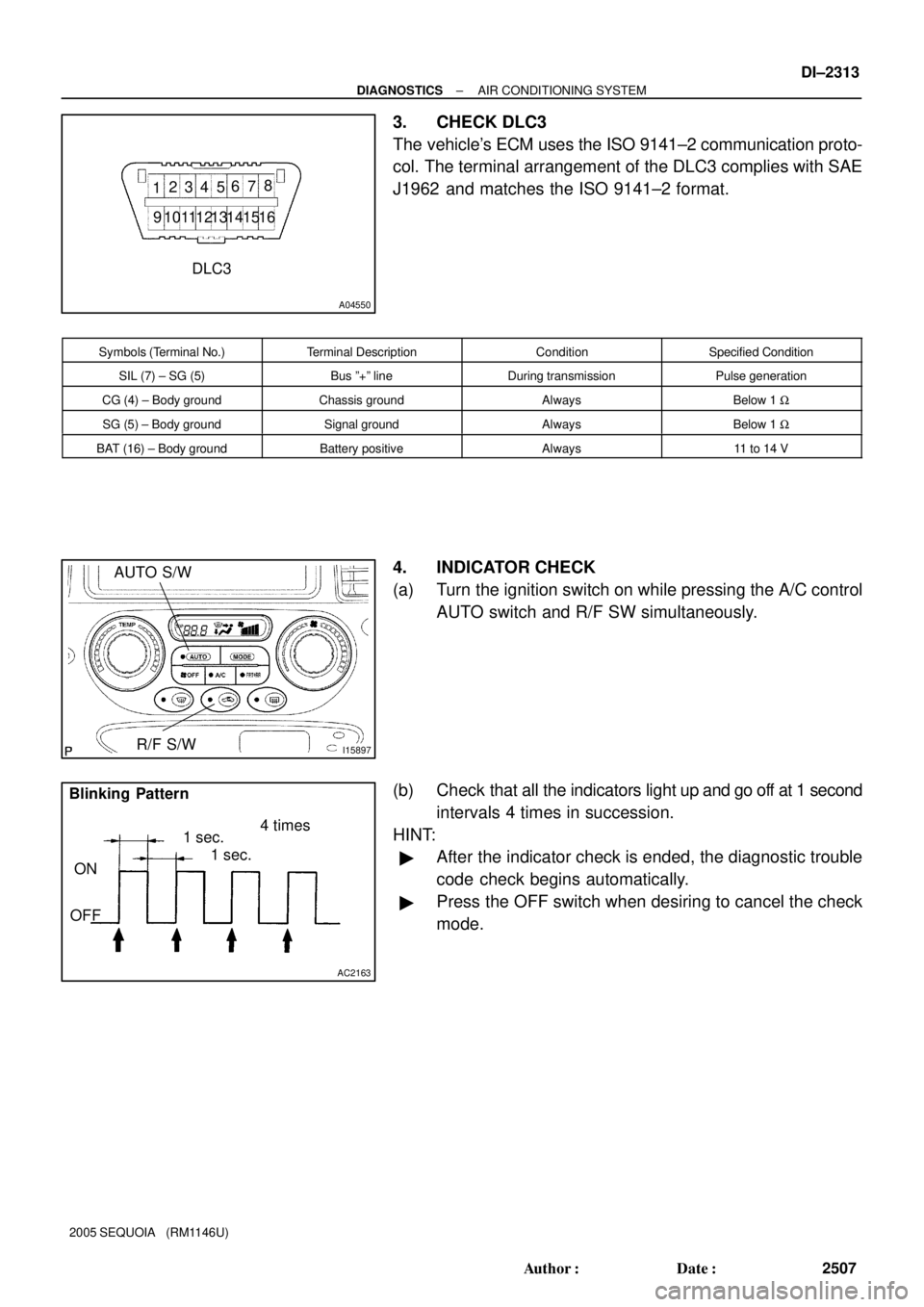
A04550
12345678
9 1 0 111 21 31 41 51 6
DLC3
I15897
AUTO S/W
R/F S/W
AC2163
Blinking Pattern
4 times
1 sec.
1 sec.
ON
OFF
± DIAGNOSTICSAIR CONDITIONING SYSTEM
DI±2313
2507 Author�: Date�:
2005 SEQUOIA (RM1146U)
3. CHECK DLC3
The vehicle's ECM uses the ISO 9141±2 communication proto-
col. The terminal arrangement of the DLC3 complies with SAE
J1962 and matches the ISO 9141±2 format.
Symbols (Terminal No.)Terminal DescriptionConditionSpecified Condition
SIL (7) ± SG (5)Bus º+º lineDuring transmissionPulse generation
CG (4) ± Body groundChassis groundAlwaysBelow 1 W
SG (5) ± Body groundSignal groundAlwaysBelow 1 W
BAT (16) ± Body groundBattery positiveAlways11 to 14 V
4. INDICATOR CHECK
(a) Turn the ignition switch on while pressing the A/C control
AUTO switch and R/F SW simultaneously.
(b) Check that all the indicators light up and go off at 1 second
intervals 4 times in succession.
HINT:
�After the indicator check is ended, the diagnostic trouble
code check begins automatically.
�Press the OFF switch when desiring to cancel the check
mode.
Page 2565 of 4323
I28842
Integration Control
and Panel
IG+
Battery15 A GAUGE 3A5
3E2
I19 R±L
B±Y
5I18
Ignition Switch
21AM1
1L
W±L IG1
40 A AM11C 1C 1E
BW 8 F10
Fusible Link BlockW±L R±L
4 7 15
R±L
16Instrument Panel J/B Instrument Panel J/B
I1910
GND
140 A ALT
O
J43 J43J/C
A
A
O 2 1 Sub J/B No. 3
± DIAGNOSTICSAIR CONDITIONING SYSTEM
DI±2363
2557 Author�: Date�:
2005 SEQUOIA (RM1146U)
IG Power Source Circuit
CIRCUIT DESCRIPTION
This is the power source for the integration control and panel and servomotors, etc.
WIRING DIAGRAM
DI937±04
Page 2567 of 4323
I15901
GAUGE Fuse Instrument panel J/B
± DIAGNOSTICSAIR CONDITIONING SYSTEM
DI±2365
2559 Author�: Date�:
2005 SEQUOIA (RM1146U)
3 Check GAUGE fuse.
PREPARATION:
Remove the GAUGE fuse from the instrument panel J/B.
CHECK:
Check continuity of the GAUGE fuse.
OK:
Continuity exists.
NG Check for shot in all the harness and compo-
nents connected to the GAUGE fuse (See page
IN±35).
OK
Check and repair harness and connector between integration control and panel and battery.
Page 2568 of 4323
I24456
Integration Control
and Panel
Engine Room J/B
Battery
F10
Fusible Link
Block Instrument
Panel J/B
10 A DOMESHORT PIN R
1J3A 3E I19
2C2D
BSub J/B No. 3
BB
R581
3
54 16 6
1E
1 RR
+B DI±2366
± DIAGNOSTICSAIR CONDITIONING SYSTEM
2560 Author�: Date�:
2005 SEQUOIA (RM1146U)
Back±up Power Source Circuit
CIRCUIT DESCRIPTION
This is the back up power source for the integration control and panel. Power is supplied even when the
ignition switch is off and is used for diagnostic trouble code memory, etc.
WIRING DIAGRAM
DI3FL±10
Page 2569 of 4323
I28847
+B I19 Integration Control and Panel:
I22575
DOME Fuse Engine Room J/B
± DIAGNOSTICSAIR CONDITIONING SYSTEM
DI±2367
2561 Author�: Date�:
2005 SEQUOIA (RM1146U)
INSPECTION PROCEDURE
1 Check voltage between terminal +B of integration control and panel and body
ground.
PREPARATION:
Remove the integration control and panel with connectors still
connected.
CHECK:
Measure the voltage between terminal +B of the integration
control and panel and body ground.
OK:
Voltage : 10 to 14 V
OK Proceed to next circuit inspection shown in
problem symptoms table (See page DI±2304).
NG
2 Check DOME fuse.
PREPARATION:
Remove the DOME fuse from the engine room J/B.
CHECK:
Check continuity of the DOME fuse.
OK:
Continuity
NG Check for short in all the harness and compo-
nents connected to the DOME fuse (See at-
tached wiring diagram).
OK
Check and repair harness and connector between integration control and panel and battery.
Page 2570 of 4323
I28843
Integration Control
and Panel
ACC D
15 A CIG I18
Ignition Switch
120 1
40 A AM1
F10
Fusible Link
Block
Battery 2 Instrument Panel J/B3
P
W
B 11L1C
6P
1E AM1
140 A ALT
ACC
5 W±L
1C
8 W±L111
I19 J15
J/C
P Instrument Panel J/B
D
GND 10
I19 O O
J43 J43J/C
A
A
IG
Cowl Side Panel RH
DI±2368
± DIAGNOSTICSAIR CONDITIONING SYSTEM
2562 Author�: Date�:
2005 SEQUOIA (RM1146U)
ACC Power Source Circuit
CIRCUIT DESCRIPTION
This circuit supplies power to the integration control and panel. It supplies power to the illumination for the
clock.
WIRING DIAGRAM
DI938±04