Page 2195 of 4323
I28500
GR 1
4 3 A36
ACC Cut Relay
12 Sub J/B No. 3
3AW±R 1
2 3A
GRB C B±O
J37To ECM
J38
RAD No. 2
3
1 6AM1 212 1Instrument Panel J/B
1 2
P
3
AM1
ACC W±R
W±LALT
5
B
Battery W±RILI2
L±W
2A
2C8
2D1 Engine Room J/B
RAD No. 3
ECU±BShort Pin 3
B B
BBJ11
J10 J11 L±W
IOBR
BRS10
S9
S9S9
S9 12
10
15
161ACC
B2+
B+
GND
E Stereo Component
Amplifier Assy
1J 1E
1L 1C 1C 1FJ/C
J/C
GR
8
4 F10
Fusible Link Block WL±W L±W
I18
Ignition SW
± DIAGNOSTICSAUDIO SYSTEM
DI±1993
2187 Author�: Date�:
2005 SEQUOIA (RM1146U)
Power source circuit (Stereo component amplifier assy)
CIRCUIT DESCRIPTION
This circuit provides power to the stereo component amplifier assy.
WIRING DIAGRAM
DID9V±01
Page 2196 of 4323
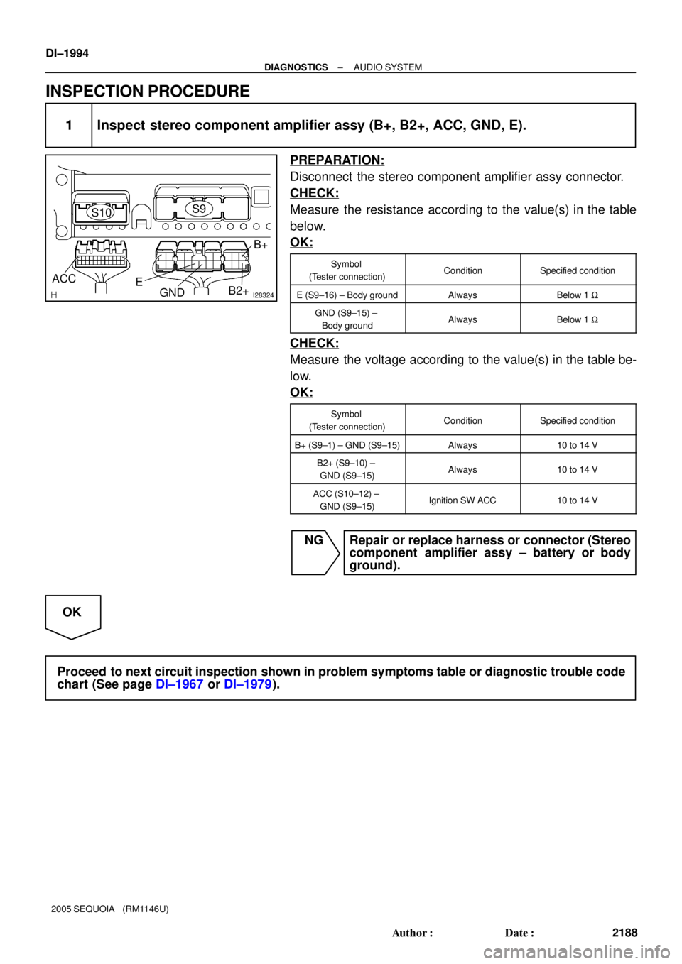
I28324GND ACC
B2+ EB+
S9S10
DI±1994
± DIAGNOSTICSAUDIO SYSTEM
2188 Author�: Date�:
2005 SEQUOIA (RM1146U)
INSPECTION PROCEDURE
1 Inspect stereo component amplifier assy (B+, B2+, ACC, GND, E).
PREPARATION:
Disconnect the stereo component amplifier assy connector.
CHECK:
Measure the resistance according to the value(s) in the table
below.
OK:
Symbol
(Tester connection)ConditionSpecified condition
E (S9±16) ± Body groundAlwaysBelow 1 W
GND (S9±15) ±
Body groundAlwaysBelow 1 W
CHECK:
Measure the voltage according to the value(s) in the table be-
low.
OK:
Symbol
(Tester connection)ConditionSpecified condition
B+ (S9±1) ± GND (S9±15)Always10 to 14 V
B2+ (S9±10) ±
GND (S9±15)Always10 to 14 V
ACC (S10±12) ±
GND (S9±15)Ignition SW ACC10 to 14 V
NG Repair or replace harness or connector (Stereo
component amplifier assy ± battery or body
ground).
OK
Proceed to next circuit inspection shown in problem symptoms table or diagnostic trouble code
chart (See page DI±1967 or DI±1979).
Page 2203 of 4323
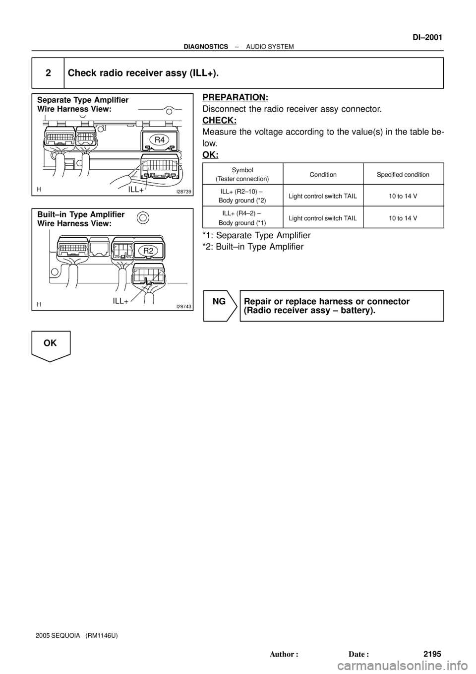
I28739
Separate Type Amplifier
Wire Harness View:
R4
ILL+
I28743
Built±in Type Amplifier
Wire Harness View:
R2
ILL+
± DIAGNOSTICSAUDIO SYSTEM
DI±2001
2195 Author�: Date�:
2005 SEQUOIA (RM1146U)
2 Check radio receiver assy (ILL+).
PREPARATION:
Disconnect the radio receiver assy connector.
CHECK:
Measure the voltage according to the value(s) in the table be-
low.
OK:
Symbol
(Tester connection)ConditionSpecified condition
ILL+ (R2±10) ±
Body ground (*2)Light control switch TAIL10 to 14 V
ILL+ (R4±2) ±
Body ground (*1)Light control switch TAIL10 to 14 V
*1: Separate Type Amplifier
*2: Built±in Type Amplifier
NG Repair or replace harness or connector
(Radio receiver assy ± battery).
OK
Page 2208 of 4323
I28741
Separate Type Amplifier
Wire Harness View:
R19
GND
I28745
Built±in Type Amplifier
Wire Harness View:
R19
GND
I28294
Spiral Cable Sub±assy
Connector Front View:
C9
DI±2006
± DIAGNOSTICSAUDIO SYSTEM
2200 Author�: Date�:
2005 SEQUOIA (RM1146U)
7 Check harness and connector (Radio receiver assy ± Spiral cable sub±assy).
PREPARATION:
Disconnect the spiral cable sub±assy connector.
CHECK:
Measure the resistance according to the value(s) in the table
below.
OK:
Symbol
(Tester connection)ConditionSpecified condition
GND (R19±6) ±
Spiral cable terminal 10AlwaysBelow 1 W
GND (R19±6) ±
Body groundAlways10 kW or higher
NG Repair or replace wire harness or connector
(Radio receiver assy ± spiral cable sub±assy).
OK
Repair or replace wire harness or connector (Battery ± spiral cable sub±assy).
Page 2209 of 4323

8 Check light control rh")
I28576
270°
Bright
0°
DarkR6
ILL±
I28577
Light Control Rheostat
Wire Harness View:
R6
E
± DIAGNOSTICSAUDIO SYSTEM
DI±2007
2201 Author�: Date�:
2005 SEQUOIA (RM1146U)
8 Check light control rheostat.
PREPARATION:
(a) Reconnect the light control rheostat switch connector.
(b) Ignition switch is ON.
(c) Light control switch is TAIL or HEAD.
CHECK:
Measure the voltage according to the value(s) in the table be-
low.
OK:
Symbol
(Tester connection)ConditionSpecified condition
ILL± (R6±6) ±
Body groundRheostat knob to fully
counterclockwise "
fully clockwise
Below 1 V " 10 to 14 V
NG Replace light control rheostat.
OK
9 Check harness and connector (Light control rheostat ± Body ground).
PREPARATION:
Disconnect the light control rheostat connector.
CHECK:
Measure the resistance according to the value(s) in the table
below.
OK:
Symbol (Tester connection)Specified condition
E (R6±5) ± Body groundBelow 1 W
NG Repair or replace harness or connector.
OK
Repair or replace wire harness or connector (Battery ± spiral cable sub±assy).
Page 2246 of 4323
DIDAD±01
DI±2044
± DIAGNOSTICSREAR SEAT AUDIO SYSTEM
2238 Author�: Date�:
2005 SEQUOIA (RM1146U)
REAR SEAT AUDIO SYSTEM
PRECAUTION
NOTICE:
When disconnecting the battery terminal, initialize the following system after the terminal is recon-
nected.
System NameSee Page
Back Door Power Window Control SystemBE±77
Page 2253 of 4323

TERMINALS OF ECU
1. REAR SEAT AUDIO CONTROLLER
Terminals No. (Symbols)Wiring ColorTermi")
DIDAL±01
I28334
R24
± DIAGNOSTICSREAR SEAT AUDIO SYSTEM
DI±2051
2245 Author�: Date�:
2005 SEQUOIA (RM1146U)
TERMINALS OF ECU
1. REAR SEAT AUDIO CONTROLLER
Terminals No. (Symbols)Wiring ColorTerminal
DescriptionConditionSpecified value
R24±1 ± Body ground
(SGN1 ± Body ground)Shielded ±
Body groundGroundAlwaysBelow 1 V
R24±2 ± R24±17
(HP1L ± GND)BR ± LGSound signal
(Output)RSA system is sounding (Headphone)
A waveform syn-
chronized with
sounds is output
R24±3 ± R24±17
(HP1R ± GND)BR ± LGSound signal
(Output)RSA system is sounding (Headphone)
A waveform syn-
chronized with
sounds is output
R24±6 ± R24±17
(R±L± ± GND)W ± LGSound signal
(Input)RSA system is sounding
A waveform syn-
chronized with
sounds is output
R24±7 ± R24±17
(R±L+ ± GND)W ± LGSound signal
(Input)RSA system is sounding
A waveform syn-
chronized with
sounds is output
R24±8 ± R24±17
(R±R± ± GND)W ± LGSound signal
(Input)RSA system is sounding
A waveform syn-
chronized with
sounds is output
R24±9 ± R24±17
(R±R+ ± GND)W ± LGSound signal
(Input)RSA system is sounding
A waveform syn-
chronized with
sounds is output
R24±10 ± Body ground
(SG1 ± Body ground)Shielded ±
Body groundGroundAlwaysBelow 1 V
R24±11 ± R24±17
(RMUT ± GND)LG ± LGMute signalAudio system is playing " Changing modeAbove 3.5 V "
Below 1 V
R24±12 ± R24±17
(+B ± GND)LG ± LGBatteryAlways10 to 14 V
R24±13 ± Body ground
(SGN2 ± Body ground)Shielded ±
Body groundGroundAlwaysBelow 1 V
R24±14 ± R24±17
(HP2L ± GND)BR ± LGSound signal
(Output)RSA system is sounding (Headphone)
A waveform syn-
chronized with
sounds is output
R24±15 ± R24±17
(HP2R ± GND)BR ± LGSound signal
(Output)RSA system is sounding (Headphone)
A waveform syn-
chronized with
sounds is output
R24±17 ± Body ground
(GND ± Body ground)LG ±
Body groundGroundAlwaysBelow 1 W
Page 2260 of 4323
DIDAM±01
I28496
B±O
24R24
Rear Seat Audio
Controller Assy
ACC
+B
17
GND 1228 C
4 3A36
ACC Cut
Relay
B 12 1Sub J/B No.3
3A
ID2 W±R
J/C
L±Y1
2
IA1 26 L±R
L±R
2B3
2C8
2D Engine Room J/B
ECU±BShort Pin
1 Instrument Panel J/B
W±R
AM11
3 2RAD No.2
W 1
P6
ALT
1B
BatteryLG To ECM
GR
RSE
2 2
1Engine Room R/B No.2J37
ID221
IMLG 3A
LG
12
ID2 J38
L±R
2 12
W±LRAD No.1
W±R
W±L 1
2B
3
AM1B
ACC
I18
Ignition SW 1C
1C 1E1F
1J
1LGR
PW±R
GR
W±B 58
4F10
Fusible Link Block DI±2058
± DIAGNOSTICSREAR SEAT AUDIO SYSTEM
2252 Author�: Date�:
2005 SEQUOIA (RM1146U)
CIRCUIT INSPECTION
Power source circuit (Rear seat audio controller)
CIRCUIT DESCRIPTION
This circuit provides the power to the rear seat audio controller.
WIRING DIAGRAM