Page 2070 of 4323
DI±1868
± DIAGNOSTICSBACK DOOR CONTROL SYSTEM
2062 Author�: Date�:
2005 SEQUOIA (RM1146U)
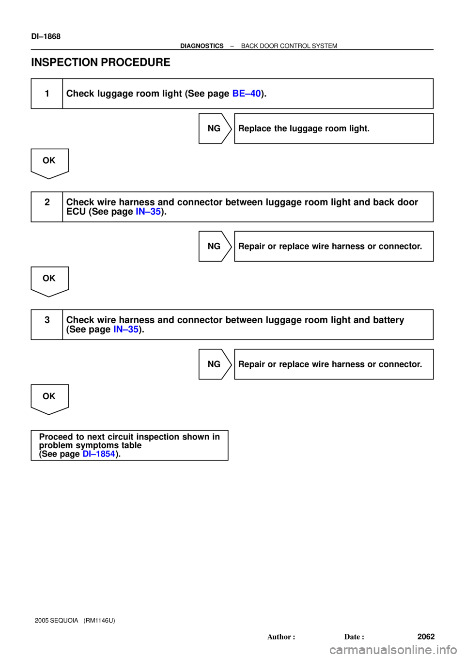
INSPECTION PROCEDURE
1 Check luggage room light (See page BE±40).
NG Replace the luggage room light.
OK
2 Check wire harness and connector between luggage room light and back door
ECU (See page IN±35).
NG Repair or replace wire harness or connector.
OK
3 Check wire harness and connector between luggage room light and battery
(See page IN±35).
NG Repair or replace wire harness or connector.
OK
Proceed to next circuit inspection shown in
problem symptoms table
(See page DI±1854).
Page 2089 of 4323
DIDF6±01
± DIAGNOSTICSMULTIPLEX COMMUNICATION SYSTEM
DI±1887
2081 Author�: Date�:
2005 SEQUOIA (RM1146U)
MULTIPLEX COMMUNICATION SYSTEM
PRECAUTION
NOTICE:
When disconnecting the battery terminal, initialize the following system after the terminal is recon-
nected.
System NameSee Page
Back Door Power Window Control SystemBE±77
Page 2091 of 4323
DIDFN±01
B78765I28978
Battery
Serial Communication Switch
ECUOn On
Off
ECULight
Motor
Heater
Solenoid � Conceptual Drawing �
I28977
Frame
Data
Header End Message
± DIAGNOSTICSMULTIPLEX COMMUNICATION SYSTEM
DI±1889
2083 Author�: Date�:
2005 SEQUOIA (RM1146U)
SYSTEM DESCRIPTION
Basic of MPX (Multiplex Communication)
1. General
The SEQUOIA multiplex communication system uses serial communication, which converts multiple pieces
of information into serial communication data. As a result, they can be transmitted through a single commu-
nication wire.
Serial communication data consists of bits and frames. A bit is the basic unit that represents the amount of
information. A bit is represented by a binary value º0º or º1º. A frame is a body of data that is transmitted
together. A frame contains a ºheaderº that indicates the beginning of the data and an ºend messageº that
indicates the end of the data.
Page 2105 of 4323

DIAGNOSIS SYSTEM
1. DIAGNOSIS SYSTEM
(a) Inspect the battery voltage.
Battery v")
DIDF8±01
C00083DLC3
± DIAGNOSTICSMULTIPLEX COMMUNICATION SYSTEM
DI±1903
2097 Author�: Date�:
2005 SEQUOIA (RM1146U)
DIAGNOSIS SYSTEM
1. DIAGNOSIS SYSTEM
(a) Inspect the battery voltage.
Battery voltage: 11 to 14 V
If voltage is below 11 V, recharge the battery before proceeding.
(b) Check the DLC3.
The body ECU uses ISO 9141±2 for communication. The
terminal arrangement of the DLC3 complies with SAE
J1962 and matches the ISO 9141±2 format.
Verify the conditions listed in the table below:
Symbols (Terminals No.)Terminal DescriptionConditionSpecified Condition
SIL(7) ± SG(5)Bus º+º lineDuring communicationPulse generation
SG(5) ± Body groundSignal groundAlwaysBelow 1 W
BAT(16) ± Body groundBattery positiveAlways11 to 14 V
HINT:
If the hand±held tester display shows UNABLE TO CONNECT
TO VEHICLE when the cable of the hand±held tester is con-
nected to the DLC3, the ignition switch is turned to the ON posi-
tion and the tester is operated, there is a problem on either the
vehicle side or the tester side.
�If communication is normal when the tester is connected
to another vehicle, inspect the DLC3 on the original ve-
hicle.
�If communication is still not possible when the tool is con-
nected to another vehicle, the problem is probably in the
tester itself, so consult the Service Department listed in
the tester's instruction manual.
Page 2111 of 4323
I28467
F18
Front Passenger Door ECUD22
Driver Door ECU
Body ECU
J/C
I18
Ignition Switch
Instrument Panel J/B
Sub J/B No. 3
F10
FL Block
Sub J/B No. 3Instrument Panel J/B
Engine Room R/B J8
J/C
Battery
IEECU±B
Short Pin
ECU±IG
AM1
PWR No. 1 J/CB7 IB1
II2
J6 J7
J37 J38IB1
IB1
IB1
3C 3A 1F 1C
1L
1E 1J
2D 2C1C
1F
3C 3A ALTIG1 AM1IB1MPX1
MPX2
GND
SIGCPUB
BDR MPX2
MPX1W±L
W±R
L±W G±B
W±B
B±RW±L
G±B
G±B
W±B
B±RW±R
W±L
B±Y
B±RB±R
W±L
L±W
W±RW
W±R
W±R BBD
AF
AA48
9 1122
23
251 3
13 20
13 8
21
88 4 4
1
1 6
12
48 5
11 23
1821
± DIAGNOSTICSMULTIPLEX COMMUNICATION SYSTEM
DI±1909
2103 Author�: Date�:
2005 SEQUOIA (RM1146U)
WIRING DIAGRAM
Page 2114 of 4323
I28468
MPX2MPX1 D22
Driver Door ECU
Back Door ECU
IB1F18
Passenger
Door ECU
J/CII2
BF1 BD2 B11
J37 J38J/CJ34 J33 II2
II2MPX2
MPX1
SIG
BDR
GND F18 F18
F18 F18
F18 F18
F18 F18
F18 F18
F18 F18 G±B
B
B±R G±B G±B
BB B B
B±R
B±R
B±R B±Y
W±L
L±Y
L±Y
B
W±R
W±R
W±R
W±R
W±B A J12
J/C
Battery
IFII2
II2 Sub J/B No. 3
3D 3A11
611
13 8(*1) (*2) 23 12(*1) (*2) 2520
(*1)(*2) 21 19(*1) (*2) 20 10(*1) (*2) 811(*1) (*2)
Engine Room J/B
ECU±B
Short Pin
2D 2C18Instrument Panel J/B
1E 1J2 3II2 F10
Fusible Link Block
ALT
48 5Instrument Panel J/B
ECU±IG
AM1
PWR No. 2 1F 1C
1L 1C
1F 44
1
176
12 Sub J/B No. 3
3C 3A88I18
Ignition SW
IG1 AM14 8
8 2 1
14AG
2 7
(*1): w/ Driving Position Memory
(*2): w/o Driving Position Memory20
AA
3
B1
W±BCPUB W DI±1912
± DIAGNOSTICSMULTIPLEX COMMUNICATION SYSTEM
2106 Author�: Date�:
2005 SEQUOIA (RM1146U)
WIRING DIAGRAM
Page 2143 of 4323
I28469
I19
Integration Control
and Panel
Body ECU
I18
Ignition SW Combination Meter
F10
FL Block
To Ignition
Switch J43
J/C
IG BatteryDOME ALTAM1CIG
ACC
AM1
Short Pin
J/CMPX±
ACC
+B MPX+ MPX2
IG+
GND C5
B5
J15
1E
1L
1JJ15
1E1C
1C
2D 2C3A 3E
3A 3E
O BR WW±L
O BRPP
P
R
R±L
R±L L±Y LG±B
DD 32
2413
3
11
31 1
1
8 6 20
1
52 8 5
4
13
6 6 16
151
2
10 Instrument Panel J/B
Engine Room J/BSub J/B No.3
AA
± DIAGNOSTICSMULTIPLEX COMMUNICATION SYSTEM
DI±1941
2135 Author�: Date�:
2005 SEQUOIA (RM1146U)
WIRING DIAGRAM
Page 2146 of 4323
I28470
Back Door ECUCombination Meter
I19
A/C ECU
(Integration Control and Panel)
Instrument Panel J/B
I18
Ignition SW
Engine Room J/B
Instrument Panel J/B
J8
J/C F10
Fusible
Link Block
Battery
IEC6 B11
BF1BD2
J34J33C5
C5
C6 1J
1C1D
1H
1J 1C
2C 2D
2C
1D 1F C6 Short Pin
ECU±B
AM2IGN1
IG2 AM2MPX1
MPX±LG±B LG±RLG±R
LG±R
LG±B
W±R
B±O W±R
B±R
W±R W±R
W±R
W±R
W±B
BR B
BABH 231
32
23
24 67
13
3
29
11
5 637
1 8
1
9
612
5 4J/C DI±1944
± DIAGNOSTICSMULTIPLEX COMMUNICATION SYSTEM
2138 Author�: Date�:
2005 SEQUOIA (RM1146U)
WIRING DIAGRAM


Instrument Panel J/B
I18
Ignition SW
Engine Room J/B
Instrument Panel J/B
J8
J/C F10
Fusible
Link Block
Battery
IEC6 B")