Page 1939 of 4323
I24356
32
1J 1E W±RBody ECU
RDA ECU±B
4
52D
5
4
B5PRG B
OW±R
B5 5
IG1
BatterySHORT PIN Engine Room J/B
1
2C8
Sub J/B No. 3
3A2
3A1
RDA PRG W2
Wireless Door
Control Receiver
+B
EV
R±G 3
2 W±RInstrument Panel J/B
F10
Fusible
Link
Block
BW±R
A J43
J/C
O
A
± DIAGNOSTICSBODY CONTROL SYSTEM
DI±1737
1931 Author�: Date�:
2005 SEQUOIA (RM1146U)
Wireless door lock receiver circuit
CIRCUIT DESCRIPTION
The signal from the transmitter is sent to the body ECU through RDA line of the wireless door control receiver.
RDA line is diagnosed by the body ECU, check DTC also in case of the failure of the wireless function.
WIRING DIAGRAM
DI6LV±13
Page 1951 of 4323
± DIAGNOSTICSBODY CONTROL SYSTEM
DI±1749
1943 Author�: Date�:
2005 SEQUOIA (RM1146U)
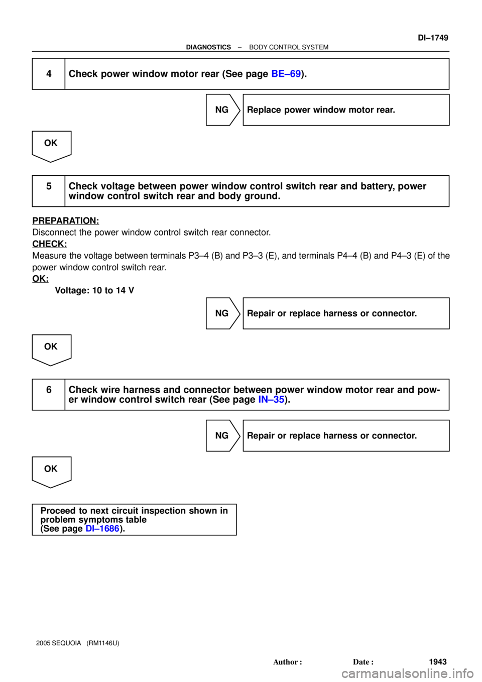
4 Check power window motor rear (See page BE±69).
NG Replace power window motor rear.
OK
5 Check voltage between power window control switch rear and battery, power
window control switch rear and body ground.
PREPARATION:
Disconnect the power window control switch rear connector.
CHECK:
Measure the voltage between terminals P3±4 (B) and P3±3 (E), and terminals P4±4 (B) and P4±3 (E) of the
power window control switch rear.
OK:
Voltage: 10 to 14 V
NG Repair or replace harness or connector.
OK
6 Check wire harness and connector between power window motor rear and pow-
er window control switch rear (See page IN±35).
NG Repair or replace harness or connector.
OK
Proceed to next circuit inspection shown in
problem symptoms table
(See page DI±1686).
Page 1966 of 4323
I24147
B7
HORN HORN Relay
2
1Body ECU
1
2D18
HR
HORN
B5 B±Y
6 C9
Horn SW
B54 F10
FL Block H8
Horn (low)
1
1 B B8
2H
7
2F5
3W±R W±R19
IA1
26
Battery H7
Horn (high)Engine Room J/B
B DI±1764
± DIAGNOSTICSBODY CONTROL SYSTEM
1958 Author�: Date�:
2005 SEQUOIA (RM1146U)
Horn circuit
CIRCUIT DESCRIPTION
The vehicle horn sounds when the horn switch is pressed. It also sounds as an alarm for the theft deterrent
system when the body ECU detects any alert condition.
WIRING DIAGRAM
DI94T±08
Page 1970 of 4323
I28524
AB
C D F P 1
2 3
45 6
7828 2930
8
7 11
6 20
13
14 13
14PP P±L
A
BBB Y Y
Y Y M+
MSW
E
B
MF8
MR
E2 R5
Remote Control
Mirror Switch
Body ECU
MIRB
MIRS
MIRE G±B
LG±B
Instrument Panel J/B
J14 J15J/C
1C 1E
1L
1C
12CIG
AM1 F10
FL BlockI18
Ignition Switch
R18
Remote Control Mirror RHB5
B5
B5
LGLG
LG
LG W±B
IMMF MRJ6
J6
J6
J6J7
J7AM1 ACC
13
W±L W ALT
B
II1
II1
R17
Remote Control Mirror LH
Battery *1 *1J/C
(*1): Control Circuit
MF MR
DI±1768
± DIAGNOSTICSBODY CONTROL SYSTEM
1962 Author�: Date�:
2005 SEQUOIA (RM1146U)
WIRING DIAGRAM
Page 1972 of 4323
DI±1770
± DIAGNOSTICSBODY CONTROL SYSTEM
1964 Author�: Date�:
2005 SEQUOIA (RM1146U)
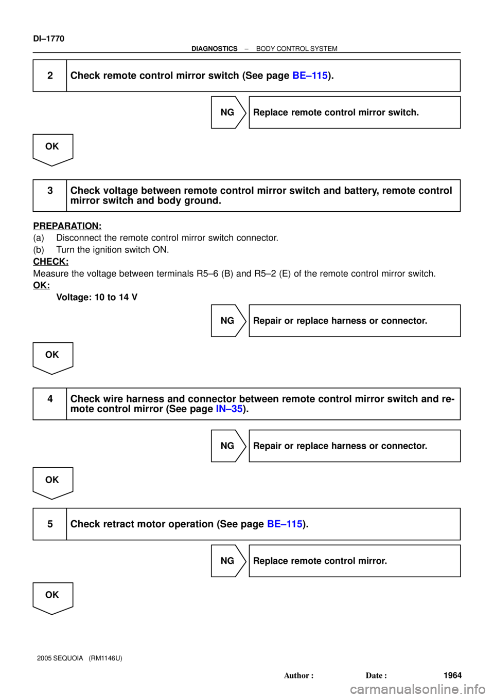
2 Check remote control mirror switch (See page BE±115).
NG Replace remote control mirror switch.
OK
3 Check voltage between remote control mirror switch and battery, remote control
mirror switch and body ground.
PREPARATION:
(a) Disconnect the remote control mirror switch connector.
(b) Turn the ignition switch ON.
CHECK:
Measure the voltage between terminals R5±6 (B) and R5±2 (E) of the remote control mirror switch.
OK:
Voltage: 10 to 14 V
NG Repair or replace harness or connector.
OK
4 Check wire harness and connector between remote control mirror switch and re-
mote control mirror (See page IN±35).
NG Repair or replace harness or connector.
OK
5 Check retract motor operation (See page BE±115).
NG Replace remote control mirror.
OK
Page 1977 of 4323
I28589
Glass Breakage
Sensor ECU
G5 Glass Breakage
Sensor Microphone
(Shielded) G4 GBSI
MI+
MI±
GND
GBIG
GB+BMIC
GNDBody ECU
DOP B5
G4
G4
G4
G4
G4Sub J/B No. 4
Sub J/B No. 3 4C 4D
3B 3A
Instrument Panel J/B
F10
Fusible LBI18
Ignition SW
Engine Room J/BHTR
AM1 1E
1J
1L1C
1E
1C
ALT
2C 2DECU±BShort Pin
Battery
IG AM1 IG1J43
J/CA
A
81
45 812 4
2
6 3 4
1 W±R
W
BW±L
B W±RB±Y W±R
O 11
R±Y R±Y33O
18 4
6 3
5P
439
B
2 1
± DIAGNOSTICSBODY CONTROL SYSTEM
DI±1775
1969 Author�: Date�:
2005 SEQUOIA (RM1146U)
WIRING DIAGRAM
Page 1980 of 4323
DIDEI±01
DI±1778
± DIAGNOSTICSDRIVER DOOR CONTROL SYSTEM
1972 Author�: Date�:
2005 SEQUOIA (RM1146U)
DRIVER DOOR CONTROL SYSTEM
PRECAUTION
NOTICE:
When disconnecting the battery terminal, initialize the following system after the terminal is recon-
nected.
System NameSee Page
Back Door Power Window Control SystemBE±77
Page 1981 of 4323
DIDEK±01
I28584
From
Battery
From
Ignition Switch To Rear
Power Window
SW RH PWR No. 3
Power Main
Driver Door ECU
(Power Window Master Switch)To Rear
Power Window
SW LH PWR No. 4From
Battery From
Battery
ECU±IG
PWR No.1
ECU±B IG +BSIG
BDR
CPUB
CPU
Window
Lock
Switch WLSW
MPX1
GND
MPX2 Passenger
Door ECU
Body ECUDriver Door Power Window Motor
DOWN
UP
Pulse Sensor
Limit Switch DU
DDN
PLS
LMT
SGND
CTYB
Driver Side Door
Courtesy LightRemote Control Mirror LH
DM+R
DMHR
DMVRLEFT
RIGHT
DOWN UP
DVC
VSSR
HSSR
LE1 LSWD
KL
KUL
BEAN Door Unlock
Detection Switch
Door Key Lock and
Unlock Switch
LSWEDOWN
UPOUT
IN PCYLEngine Room J/B
± DIAGNOSTICSDRIVER DOOR CONTROL SYSTEM
DI±1779
1973 Author�: Date�:
2005 SEQUOIA (RM1146U)
SYSTEM DIAGRAM


1
1 B B8
2H
7
2F5
3W±R W±R19
IA1
26
Battery H7
Horn (high)Engine Room J/B
B DI±1764
± DIAG")

 G4 GBSI
MI+
MI±
GND
GBIG
GB+BMIC
GNDBody ECU
DOP B5
G4
G4
G4
G4
G4Sub J/B No. 4
Sub J/B No. 3 4C 4D
3B 3A
Instrument")

To Rear
Power Window
SW LH PWR No. 4From
Battery From
Bat")