Page 1831 of 4323
I28557
I18
Ignition SWInstrument Panel J/BCombination Meter
Engine Room J/B
Sub J/B No. 4
IEBattery J8
J/CIA5 F10
Fusible
Link BlockC6
C5 C6
C6
C5 1F
1J
1C1D
1H
1C
1C1D
1D
1J
1J
2C 2D
222C
4B 4A AM2IG2
ST2
(*1) (*2)
W±B
W±R
B±R
B±WBR
B±O W±R
B±R
W±R W±RB±R
B±R B
AB
B
BB 893
98
2
1 1
1 4
5Short Pin
ECU±B
AM2
STA 4 5
8 211 9
37 6
53 396
IGN1
IGN212
23
24
28
Engine Room R/B
*1: Head (USA)
*2: Tail (CANADA)
± DIAGNOSTICSCOMBINATION METER SYSTEM
DI±1629
1823 Author�: Date�:
2005 SEQUOIA (RM1146U)
WIRING DIAGRAM
Page 1834 of 4323
I28558
C612
W±B
Battery AW
58BR
IECombination Meter
W±L I18
Ignition SW
2 1
AM1 IG1
B±Y
W Instrument Panel J/B
AM1
21 47
6 1 6
9 1C
1C
1D 1E
1L
1FR±L
R±LSub J/B No. 3
3B 3A515C524
C610 R±L
Y±RY
Y±RY
13
23 19
26
IG4
IG4
IG4
GAUGE
B V1
Vehicle Speed Sensor
(Combination Meter)
F10
Fusible Link Block
J8
J/C DI±1632
± DIAGNOSTICSCOMBINATION METER SYSTEM
1826 Author�: Date�:
2005 SEQUOIA (RM1146U)
Malfunction in speedometer
CIRCUIT DESCRIPTION
The speedometer detects vehicle speed based on a 4±pulse signal from the vehicle speed sensor.
WIRING DIAGRAM
DID8Z±01
Page 1836 of 4323
N02332
1
2 3
DI±1634
± DIAGNOSTICSCOMBINATION METER SYSTEM
1828 Author�: Date�:
2005 SEQUOIA (RM1146U)
3 Inspect vehicle speed sensor.
PREPARATION:
(a) Disconnect the vehicle speed sensor connector.
(b) Connect the positive (+) lead from the battery to terminal
1 and the negative (±) lead to terminal 2.
(c) Connect the positive (+) lead from the tester to terminal
3 and the negative (±) lead to terminal 2.
(d) Rotate the shaft.
CHECK:
Check that voltage between terminals 2 and 3 changes from
approx. 0 V to16 V or more.
OK:
Voltage changes from approx. 0 V to 16 V
HINT:
The voltage should change 4 times for every revolution of the
speed sensor shaft.
NG Replace vehicle speed sensor.
OK
Page 1837 of 4323
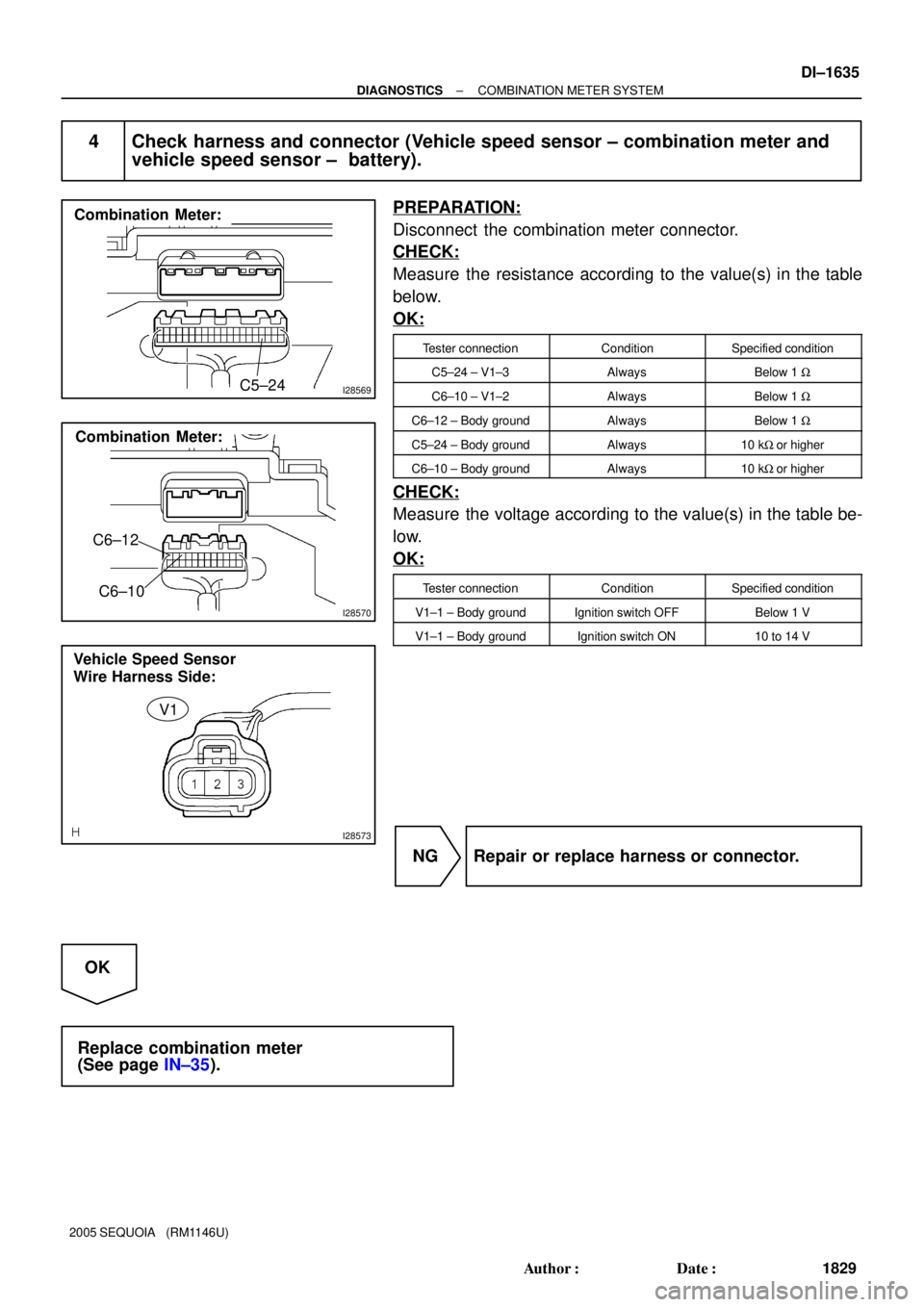
I28569
Combination Meter:
C5±24
I28570
Combination Meter:
C6±12
C6±10
I28573
Vehicle Speed Sensor
Wire Harness Side:
V1
± DIAGNOSTICSCOMBINATION METER SYSTEM
DI±1635
1829 Author�: Date�:
2005 SEQUOIA (RM1146U)
4 Check harness and connector (Vehicle speed sensor ± combination meter and
vehicle speed sensor ± battery).
PREPARATION:
Disconnect the combination meter connector.
CHECK:
Measure the resistance according to the value(s) in the table
below.
OK:
Tester connectionConditionSpecified condition
C5±24 ± V1±3AlwaysBelow 1 W
C6±10 ± V1±2AlwaysBelow 1 W
C6±12 ± Body groundAlwaysBelow 1 W
C5±24 ± Body groundAlways10 kW or higher
C6±10 ± Body groundAlways10 kW or higher
CHECK:
Measure the voltage according to the value(s) in the table be-
low.
OK:
Tester connectionConditionSpecified condition
V1±1 ± Body groundIgnition switch OFFBelow 1 V
V1±1 ± Body groundIgnition switch ON10 to 14 V
NG Repair or replace harness or connector.
OK
Replace combination meter
(See page IN±35).
Page 1848 of 4323
I28561
R6
Rheostat
To Each
Illumination Parts
To Each
Illumination Parts
Instrument Panel J/B
Combination Meter
I18
Ignition SW J8
J/C
Sub J/B No. 3
F10
Fusible Link Block
Engine Room J/B
Battery
IET
ILL±
E
TR
IG C5
C612 22
24
C6
Illumination 1F
1J 1C1D 1H
1C
1C8
2
11 9
34 13
6
IGN1
AM11H 1E
1C4
1 1F
1L 6
7 56
12
2DECU±IG
2188
3A 3E
8
4
51 3 4
5 6
ALT
AM2 IG2
AM2 11
2C A
A
AM1 IG1
G
W±G
W±B
BR W±G
W±G
W±BW±G
B±R
B±YB±O
B±R
W
W±L
W±RB±R
BW±RB DI±1646
± DIAGNOSTICSCOMBINATION METER SYSTEM
1840 Author�: Date�:
2005 SEQUOIA (RM1146U)
WIRING DIAGRAM
Page 1852 of 4323
I28562
Combination Meter
Instrument Panel J/B
Engine Room J/B I18
Ignition SW Front Seat
Inner Belt
(Buckle
SW LH)
*1: w/ Power Seat
*2: w/o Power Seat Battery
BH IEJ8
J/C
F10
FLB BI2J24
J/C
4
5
BB B
B
AC5
C6
12 24
C64
Seat
BeltBuzzer
2D2C 11
AM2 1F 1C
1D1H
1C
1J 211
9 3
7
6 IGN1
56
AM2 IG2
W±BB±O
BR
W±R W±B
(*1)(*2)
W±B
(*1) W±B
(*1)(*1) (*2) (*1)(*1) (*1) G±Y G±YG±Y
(*2)
1 33 213
B16 B16 B16 B16
W±RG±Y
B±R W±RBI2 IN1
313
W±B
(*2)
DI±1650
± DIAGNOSTICSCOMBINATION METER SYSTEM
1844 Author�: Date�:
2005 SEQUOIA (RM1146U)
Seat belt warning for driver's seat does not operate
CIRCUIT DESCRIPTION
A buzzer and indicator are included in the seat belt warning system. When the ignition switch is ON and the
seat belt on the driver side is not fastened, both the buzzer and indicator operate.
The buzzer and indicator are built into the combination meter.
WIRING DIAGRAM
DID94±01
Page 1860 of 4323
I28564
I18
Ignition SWInstrument Panel J/BCombination Meter
Engine Room J/B F10
Fusible LB
BatteryIGN1
AM2
AM2 IG2
2D 2C11 1C 1H
1C1J 2
11
37 56B±R B±O
W±R
BB
4 5C624
W±R DI±1658
± DIAGNOSTICSCOMBINATION METER SYSTEM
1852 Author�: Date�:
2005 SEQUOIA (RM1146U)
Malfunction in volt meter
CIRCUIT DESCRIPTION
The voltmeter indicates the voltage applied to the IG terminal of the combination meter.
WIRING DIAGRAM
DID96±01
Page 1863 of 4323
DID64±01
± DIAGNOSTICSSLIDING ROOF SYSTEM
DI±1661
1855 Author�: Date�:
2005 SEQUOIA (RM1146U)
SLIDING ROOF SYSTEM
PRECAUTION
NOTICE:
When disconnecting the battery terminal, initialize the following system after the terminal is recon-
nected.
System NameSee Page
Back Door Power Window Control SystemBE±77


*1: w/ Power Seat
*2: w/o Power Seat Battery
BH IEJ8
J/C
F10
FLB BI2J24
J/C
4
5
BB")