Page 2306 of 4323

DI±2104
± DIAGNOSTICSREAR SEAT ENTERTAINMANT SYSTEM
2298 Author�: Date�:
2005 SEQUOIA (RM1146U)DC
*4
Transmission Error
Transmission to component shown by sub±code
failed.
(This code does not necessarily mean actual fail-
ure.)If same sub±code is recorded in
other component(s), check harness
for power supply and communica-
tion system of all components
shown by code.
±
DE
*3Slave Reset (Momentary Inter-
ruption)After engine start, slave component has been dis-
connected.
1. Power source circuit (Television
display assy).
2. Power source circuit (Disc play-
er controller).
3. AVC±LAN circuit
4. Replace television display assy.
5. Replace disc player controller.DI±2107
DI±2112
DI±2139
±
±
E4
*1Multiple Frame AbortMultiple frame transmission is aborted.
Since this DTC is provided for engi-
neering purpose, it may be detected
when no actual failure exists.
±
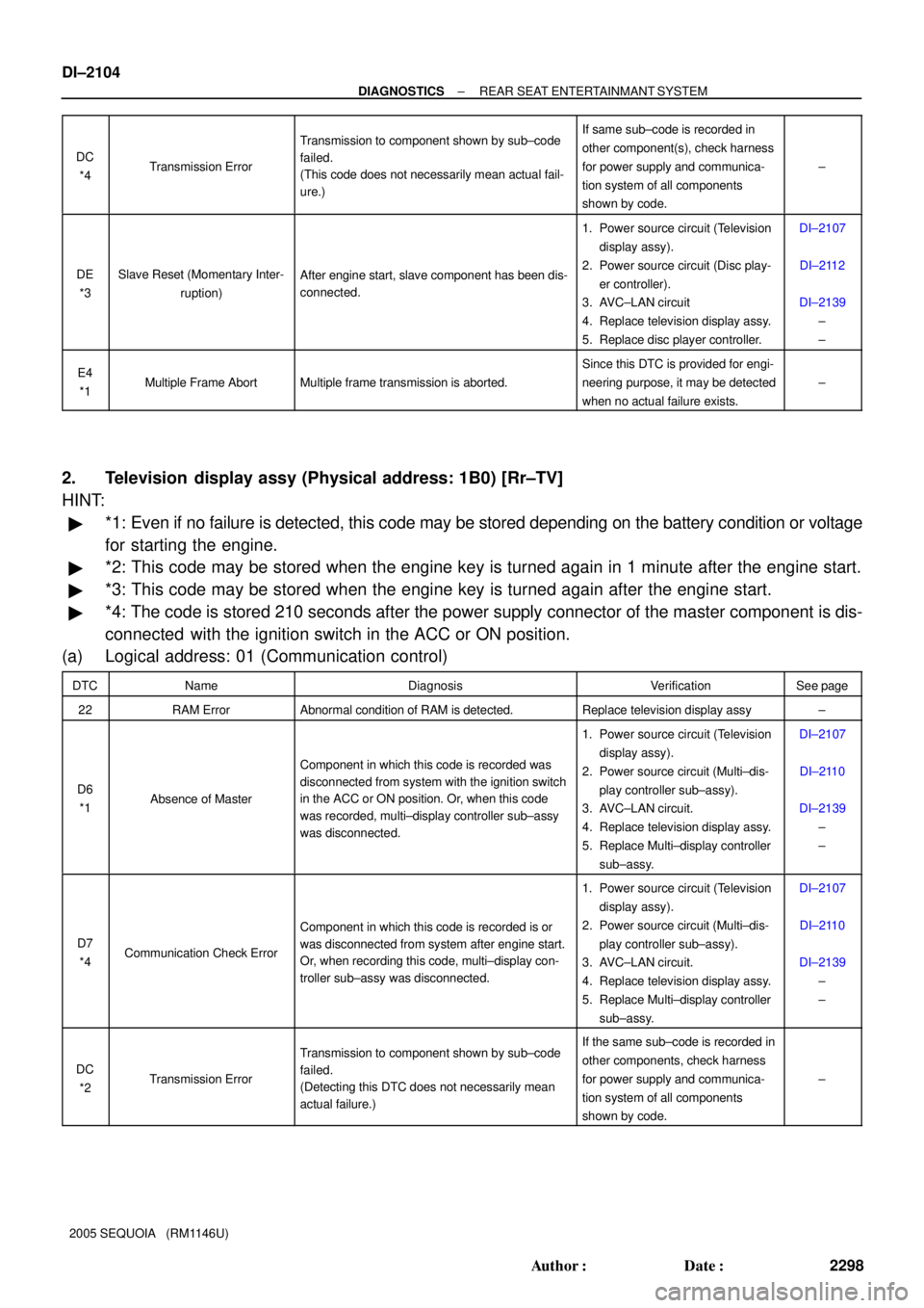
2. Television display assy (Physical address: 1B0) [Rr±TV]
HINT:
�*1: Even if no failure is detected, this code may be stored depending on the battery condition or voltage
for starting the engine.
�*2: This code may be stored when the engine key is turned again in 1 minute after the engine start.
�*3: This code may be stored when the engine key is turned again after the engine start.
�*4: The code is stored 210 seconds after the power supply connector of the master component is dis-
connected with the ignition switch in the ACC or ON position.
(a) Logical address: 01 (Communication control)
DTCNameDiagnosisVerificationSee page
22RAM ErrorAbnormal condition of RAM is detected.Replace television display assy±
D6
*1Absence of Master
Component in which this code is recorded was
disconnected from system with the ignition switch
in the ACC or ON position. Or, when this code
was recorded, multi±display controller sub±assy
was disconnected.
1. Power source circuit (Television
display assy).
2. Power source circuit (Multi±dis-
play controller sub±assy).
3. AVC±LAN circuit.
4. Replace television display assy.
5. Replace Multi±display controller
sub±assy.DI±2107
DI±2110
DI±2139
±
±
D7
*4Communication Check Error
Component in which this code is recorded is or
was disconnected from system after engine start.
Or, when recording this code, multi±display con-
troller sub±assy was disconnected.
1. Power source circuit (Television
display assy).
2. Power source circuit (Multi±dis-
play controller sub±assy).
3. AVC±LAN circuit.
4. Replace television display assy.
5. Replace Multi±display controller
sub±assy.DI±2107
DI±2110
DI±2139
±
±
DC
*2Transmission Error
Transmission to component shown by sub±code
failed.
(Detecting this DTC does not necessarily mean
actual failure.)If the same sub±code is recorded in
other components, check harness
for power supply and communica-
tion system of all components
shown by code.
±
Page 2307 of 4323

± DIAGNOSTICSREAR SEAT ENTERTAINMANT SYSTEM
DI±2105
2299 Author�: Date�:
2005 SEQUOIA (RM1146U)DD
*3
Master Reset (Momentary Inter-
ruption)After engine start, multi±display controller sub±
assy was disconnected from system.
1. Power source circuit (Television
display assy).
2. Power source circuit (Multi±dis-
play controller sub±assy).
3. AVC±LAN circuit.
4. Replace television display assy.
5. Replace Multi±display controller
sub±assy.DI±2107
DI±2110
DI±2139
±
±
DF
*4Master Error
Due to defective condition of component with a
display, master function is switched to audio
equipment.
Error occurs in communication between sub±
master (audio) and master component.
1. Power source circuit (Television
display assy).
2. Power source circuit (Multi±dis-
play controller sub±assy).
3. AVC±LAN circuit.
4. Replace television display assy.
5. Replace Multi±display controller
sub±assy.DI±2107
DI±2110
DI±2139
±
±
E0
*1Registration Completion
Instruction ErrorºRegistration Completion Instructionº command
from master cannot be received.Since this DTC is provided for engi-
neering purposes, it may be de-
tected when no actual failure exists.
±
E2ON/OFF Instruction Parameter
ErrorError occurs in ON/OFF controlling command
from multi±display controller sub±assy.Replace multi±display controller
sub±assy.±
E3
*1Registration Request Transmis-
sion
�Registration Request command is output from
slave component.
�Registration Connection Check Instruction, Reg-
istration Request command is output from sub±
master component.
Since this DTC is provided for engi-
neering purposes, it may be de-
tected when no actual failure exists.
±
E4
*1Multiple Frame AbortMultiple frame transmission is aborted.
Since this DTC is provided for engi-
neering purposes, it may be de-
tected when no actual failure exists.
±
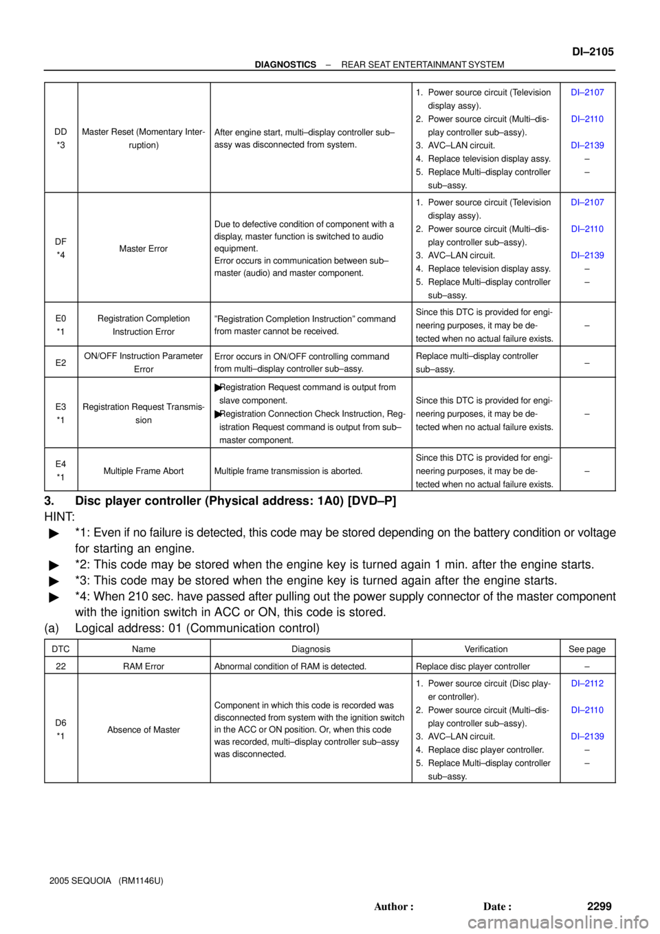
3. Disc player controller (Physical address: 1A0) [DVD±P]
HINT:
�*1: Even if no failure is detected, this code may be stored depending on the battery condition or voltage
for starting an engine.
�*2: This code may be stored when the engine key is turned again 1 min. after the engine starts.
�*3: This code may be stored when the engine key is turned again after the engine starts.
�*4: When 210 sec. have passed after pulling out the power supply connector of the master component
with the ignition switch in ACC or ON, this code is stored.
(a) Logical address: 01 (Communication control)
DTCNameDiagnosisVerificationSee page
22RAM ErrorAbnormal condition of RAM is detected.Replace disc player controller±
D6
*1Absence of Master
Component in which this code is recorded was
disconnected from system with the ignition switch
in the ACC or ON position. Or, when this code
was recorded, multi±display controller sub±assy
was disconnected.
1. Power source circuit (Disc play-
er controller).
2. Power source circuit (Multi±dis-
play controller sub±assy).
3. AVC±LAN circuit.
4. Replace disc player controller.
5. Replace Multi±display controller
sub±assy.DI±2112
DI±2110
DI±2139
±
±
Page 2309 of 4323
DIDB4±01
I28485
Multi±display
Controller Sub±assy R25
Television Display Assy
IF4
ACC
GND8
7
IF4
IF41Y
LG
Y1
2
6+B2
ACC2
GND1 BU+B
ID28
7
ID2
ID21R21
R21
R21 Y
LG
Y Y
LG
Y 8
7
1
± DIAGNOSTICSREAR SEAT ENTERTAINMANT SYSTEM
DI±2107
2301 Author�: Date�:
2005 SEQUOIA (RM1146U)
CIRCUIT INSPECTION
Power source circuit (Television display assy)
CIRCUIT DESCRIPTION
This circuit provides power to the television display assy. The power is sent from the battery to the television
display assy through the multi±display controller sub±assy.
WIRING DIAGRAM
Page 2312 of 4323
I28486
J/C Sub J/B No.3
R2332 Multi±display Controller Sub±assy
ACC
R2316
+B1
R2329
GND IF3
1
IFC
4 3A36
ACC
Cut Relay
B 1
I18
Ignition SW12
12 3A W±R
W±R
1To ECM
IA126
L±R L±R
2D1
2C8Engine Room J/B
RAD No. 1
ECU±BShort Pin 3
W±L2
W±R 1C
3
1E 1J
W
IL1
IC6AM1
8
F10
FL Block
ALT
54
B
Battery
IM13
LG GR GR
L±Y GR
2 2 Engine Room R/B No. 2
Y
IF33
W±B 3AW±R
1
IF3
22B
P
3
ACCAM1
BB 1 2 W±LB±O
J37 J38
L±YY
RAD No. 2 1Instrument Panel J/B
2
1RSE
2C P DI±2110
± DIAGNOSTICSREAR SEAT ENTERTAINMANT SYSTEM
2304 Author�: Date�:
2005 SEQUOIA (RM1146U)
Power source circuit (Multi±display controller sub±assy)
CIRCUIT DESCRIPTION
This circuit provides power to the multi±display controller sub±assy.
WIRING DIAGRAM
DIDB5±01
Page 2314 of 4323
I28487
Multi±display
Controller Sub±assy D23
Disc Player Controller
ACC
GND12
11
15+BACC3
GND4 +BR22
R22
R22 LGLG
LG 19
20
16 DI±2112
± DIAGNOSTICSREAR SEAT ENTERTAINMANT SYSTEM
2306 Author�: Date�:
2005 SEQUOIA (RM1146U)
Power source circuit (Disc player controller)
CIRCUIT DESCRIPTION
This circuit provides power to the disc player controller. The power is sent from the battery to the disc player
controller through the multi±display controller sub±assy.
WIRING DIAGRAM
DIDB6±01
Page 2359 of 4323
± DIAGNOSTICSREAR SEAT ENTERTAINMANT SYSTEM
DI±2157
2351 Author�: Date�:
2005 SEQUOIA (RM1146U)
Remote control system does not operate
INSPECTION PROCEDURE
1 Check malfunction symptoms.
CHECK:
Check for obstructions.
Check that there are no obstructions between the switch assy and the infrared ray emitting portion of
the television display assy.
OK:
No obstructions.
NG Remove obstructions.
OK
2 Check battery (Switch assy).
CHECK:
Check the battery.
Check that the dry±cell battery used for the switch assy is not dead.
OK:
It is not dead.
NG Replace dry±cell battery.
OK
DIDBN±01
Page 2361 of 4323
DIDBO±01
± DIAGNOSTICSNAVIGATION SYSTEM
DI±2159
2353 Author�: Date�:
2005 SEQUOIA (RM1146U)
NAVIGATION SYSTEM
PRECAUTION
NOTICE:
When disconnecting the battery terminal, initialize the following system after the terminal is recon-
nected.
System NameSee Page
Back Door Power Window Control SystemBE±77
Page 2389 of 4323

DIDC4±01
I28763
R27
R29R30
R26R28
± DIAGNOSTICSNAVIGATION SYSTEM
DI±2187
2381 Author�: Date�:
2005 SEQUOIA (RM1146U)
TERMINALS OF ECU
1. RADIO AND NAVIGATION ASSY
Symbols (Terminal No.)Wiring ColorTerminal DescriptionConditionSpecification
ACC (R30±11) ±
GND (R30±20)GR ± BRAccessory (ON)Ignition switch OFF
"ACC or ONBelow 1 V "10 to 14 V
B (R30±1) ± GND (R30±20)L±Y ± BRBatteryAlways10 to 14 V
GND (R30±20) ± Body groundBR ±
Body groundGroundAlwaysBelow 1 V
ANT (R30±13) ±
GND (R30±20)B±R ± BRPower source of antennaRadio switch ON and AM or FM10 to 14 V
ILL+ (R30±2) ± ILL± (R30±12)G ± W±GIllumination signal
Ignition switch ON
Light control switch OFF "TAIL or
ONBelow 1 V "
10 to 14 V
R+ (R30±8) ± GND (R30±20)W ± BRSound signal (Right)Audio system is playing
A waveform synchro-
nized with sound is out-
put
L+ (R30±9) ± GND (R30±20)B ± BRSound signal (Left)Audio system is playing
A waveform synchro-
nized with sound is out-
put
R± (R30±18) ± GND (R30±20)G ± BRSound signal (Right)Audio system is playing
A waveform synchro-
nized with sound is out-
put
L± (R30±19) ± GND (R30±20)R ± BRSound signal (Left)Audio system is playing
A waveform synchro-
nized with sound is out-
put
SWG (R27±6) ± Body groundBR±W ±
Body groundSteering pad switch
groundAlwaysBelow 1 V
SW1 (R27±7) ± SWG (R27±6)LG±R ± BR±WSteering pad switch signal
Steering pad switch not operated
"SEEK+ switch pushed
"SEEK± switch pushed
"VOL+ switch pushed
"VOL± switch pushed4 V or more
"Approx. 0.5 V
"Approx. 0.9 V
"Approx. 2.0 V
"Approx. 3.4 V