Page 1697 of 4323
H23040
LA
A20
± DIAGNOSTICSSUPPLEMENTAL RESTRAINT SYSTEM
DI±1495
1689 Author�: Date�:
2005 SEQUOIA (RM1146U)
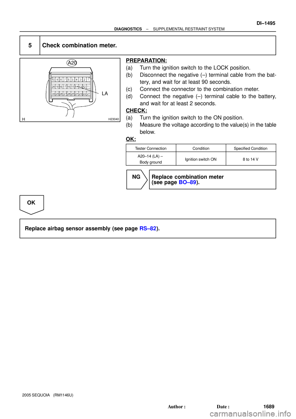
5 Check combination meter.
PREPARATION:
(a) Turn the ignition switch to the LOCK position.
(b) Disconnect the negative (±) terminal cable from the bat-
tery, and wait for at least 90 seconds.
(c) Connect the connector to the combination meter.
(d) Connect the negative (±) terminal cable to the battery,
and wait for at least 2 seconds.
CHECK:
(a) Turn the ignition switch to the ON position.
(b) Measure the voltage according to the value(s) in the table
below.
OK:
Tester ConnectionConditionSpecified Condition
A20±14 (LA) ±
Body groundIgnition switch ON8 to 14 V
NG Replace combination meter
(see page BO±89).
OK
Replace airbag sensor assembly (see page RS±82).
Page 1698 of 4323

SRS Warning Light Circuit Malfunction (Does not light up, when
ignition switch is turned to on)
CIRCU")
DI±1496
± DIAGNOSTICSSUPPLEMENTAL RESTRAINT SYSTEM
1690 Author�: Date�:
2005 SEQUOIA (RM1146U)
SRS Warning Light Circuit Malfunction (Does not light up, when
ignition switch is turned to on)
CIRCUIT DESCRIPTION
The SRS warning light is located on the combination meter assembly.
When the SRS is normal, the SRS warning light comes on for approximately 6 seconds after the ignition
switch is turned from the LOCK position to the ON position, and then goes off automatically.
If there is a malfunction in the SRS, the SRS warning light comes on to inform the driver of a problem.
When terminals TC and CG of the DLC3 are connected, the DTC is displayed by blinking the SRS warning
light.
WIRING DIAGRAM
See page DI±1491.
INSPECTION PROCEDURE
CAUTION:
Be sure to perform the following procedures before troubleshooting to avoid unexpected airbag de-
ployment.
(a) Turn the ignition switch to the LOCK position.
(b) Disconnect the negative (±) terminal cable from the battery, and wait for at least 90 seconds.
(c) Disconnect the connectors from the airbag sensor assembly.
(d) Disconnect the connectors from the steering wheel pad.
(e) Disconnect the connectors from the front passenger airbag assembly.
(f) w/ Side and curtain shield airbag:
Disconnect the connectors from the side airbag assembly LH and RH.
(g) w/ Side and curtain shield airbag:
Disconnect the connectors from the curtain shield airbag assembly LH and RH.
(h) Disconnect the connectors from the front seat outer belt LH and RH.
1 Check battery.
CHECK:
Measure the voltage of the battery.
OK:
Voltage: 11 to 14 V
NG Replace battery.
OK
DIDHV±01
Page 1699 of 4323

2 Check combination meter.
PREPARATION:
Connect the negative (±) terminal cable to th")
H23040
LA A20
± DIAGNOSTICSSUPPLEMENTAL RESTRAINT SYSTEM
DI±1497
1691 Author�: Date�:
2005 SEQUOIA (RM1146U)
2 Check combination meter.
PREPARATION:
Connect the negative (±) terminal cable to the battery, and wait for at least 2 seconds.
CHECK:
Turn the ignition switch to the ON position, check the operation of the SRS warning light.
OK:
The SRS warning light comes on (goes off 6 seconds after the ignition switch is turned to the
ON position).
NG Go to step 3.
OK
Replace airbag sensor assembly (see page RS±82).
3 Check wire harness (combination meter ± airbag sensor assembly).
PREPARATION:
(a) Turn the ignition switch to the LOCK position.
(b) Disconnect the negative (±) terminal cable from the bat-
tery, and wait for at least 90 seconds.
(c) Disconnect the connector from the combination meter.
(d) Connect the negative (±) terminal cable to the battery,
and wait for at least 2 seconds.
CHECK:
(a) Turn the ignition switch to the ON position.
(b) Measure the voltage according to the value(s) in the table
below.
OK:
Tester ConnectionConditionSpecified Condition
A20±14 (LA) ±
Body groundIgnition switch ONBelow 1 V
NG Repair or replace wire harness.
OK
Replace combination meter (see page BO±89).
Page 1700 of 4323
H24006
Airbag Sensor
Assembly
TC 15
P±B
A20 G Instrument Panel J/B Sub J/B No. 4
D6
DLC3 5
4D 5
4E
5
4B
5
4C5
4A P±B
P±B
P±B P±B 23
E4 ECM
TC
T5
Translate ECU
T17
Tire Pressure Monitor ECUTC
TC28
12 13TC
CG
4O
A
J43
J/C
IGA
O 9
1A 15
1F DI±1498
± DIAGNOSTICSSUPPLEMENTAL RESTRAINT SYSTEM
1692 Author�: Date�:
2005 SEQUOIA (RM1146U)
TC Terminal Circuit
CIRCUIT DESCRIPTION
DTC output mode is set by connecting terminals TC and CG of the DLC3.
The DTCs are displayed by blinking of the SRS warning light.
WIRING DIAGRAM
HINT:
When each warning light stays blinking, a ground short in the wiring of the terminal TC of the DLC3 or an
internal ground short in each ECU is suspected.
DIDHW±01
Page 1701 of 4323

INSPECTION PROCEDURE
CAUTION:
Be sure t")
H40173G27651H23482
DLC3:
TC
Airbag Sensor Assembly:
A20
TC
D6
± DIAGNOSTICSSUPPLEMENTAL RESTRAINT SYSTEM
DI±1499
1693 Author�: Date�:
2005 SEQUOIA (RM1146U)
INSPECTION PROCEDURE
CAUTION:
Be sure to perform the following procedures before troubleshooting to avoid unexpected airbag de-
ployment.
(a) Turn the ignition switch to the LOCK position.
(b) Disconnect the negative (±) terminal cable from the battery, and wait for at least 90 seconds.
(c) Disconnect the connectors from the airbag sensor assembly.
(d) Disconnect the connectors from the steering wheel pad.
(e) Disconnect the connectors from the front passenger airbag assembly.
(f) w/ Side and curtain shield airbag:
Disconnect the connectors from the side airbag assembly LH and RH.
(g) w/ Side and curtain shield airbag:
Disconnect the connectors from the curtain shield airbag assembly LH and RH.
(h) Disconnect the connectors from the front seat outer belt LH and RH.
1 Check wire harness (DLC3 ± airbag sensor assembly).
CHECK:
Measure the resistance according to the value(s) in the table
below.
OK:
Tester ConnectionConditionSpecified Condition
D6±13 (TC) ±
A20±15 (TC)AlwaysBelow 1 W
NG Repair or replace wire harness (TC of DLC3 ± TC
of airbag sensor assembly).
OK
Page 1703 of 4323
DIDDW±01
± DIAGNOSTICSPOWER SEAT CONTROL SYSTEM (w/ Driving Position
Memory)DI±1501
1695 Author�: Date�:
2005 SEQUOIA (RM1146U)
POWER SEAT CONTROL SYSTEM (w/ Driving Position
Memory)
PRECAUTION
NOTICE:
When disconnecting the battery terminal, initialize the following system after the terminal is recon-
nected.
System NameSee Page
Back Door Power Window Control SystemBE±77
Page 1711 of 4323
DI±1509
1703 Author�: Date�:
2005 SEQUOIA (RM1146U)
TERMINALS OF ECU
1. CHECK POSITION CONTROL ECU & SWITC")
DIDE5±01
I27716
M7M6
± DIAGNOSTICSPOWER SEAT CONTROL SYSTEM (w/ Driving Position
Memory)DI±1509
1703 Author�: Date�:
2005 SEQUOIA (RM1146U)
TERMINALS OF ECU
1. CHECK POSITION CONTROL ECU & SWITCH ASSY
(a) Disconnect the M6 and M7 ECU & switch connectors.
(b) Check the voltage of each terminal of the wire harness side connectors.
Standard:
Symbols (Terminal No.)Wiring ColorTerminal DescriptionConditionSpecified Condition
GND (M7±1) ±
Body groundW±B ± Body groundGroundAlwaysBelow 1 V
+B (M7±5) ±
GND (M7±1)L±O ± W±BBatteryAlways10 to 14 V
SYSB (M6±8) ±
GND (M7±1)W±R ± W±BPower sourceAlways10 to 14 V
IG (M6±4) ± GND (M7±1)B±R ± W±BIgnition switchIgnition switch OFF " ONBelow 1 V " 10 to 14 V
MPX1 (M6±1) ±
GND (M7±1)W ± W±BCommunication signalAlways10 kW or higher
If the result is not as specified, there may be a malfunction on the wire harness side.
(c) Reconnect the M6 and M7 ECU & switch connectors.
(d) Check the voltage of each terminal of the connectors.
Standard:
Symbols (Terminal No.)Wiring ColorTerminal DescriptionConditionSpecified Condition
SLD+ (M7±2) ±
GND (M7±1)L ± W±BSliding motor signal
(Forward)Seat moving forward using
sliding switch " Others10 to 14 V " Below 1 V
SLD± (M7±3) ±
GND (M7±1)Y ± W±BSliding motor signal
(Rearward)Seat moving rearward us-
ing sliding switch " Others10 to 14 V " Below 1 V
FRV+ (M7±6) ±
GND (M7±1)G ± W±BFront vertical motor signal
(Upward)Seat cushion front portion
raising using front vertical
switch " Others
10 to 14 V " Below 1 V
FRV± (M7±4) ±
GND (M7±1)B ± W±BFront vertical motor signal
(Downward)Seat cushion front portion
lowering using front vertical
switch " Others
10 to 14 V " Below 1 V
LFT+ (M7±7) ±
GND (M7±1)W ± W±BLifter motor signal
(Upward)Seat raising using lifter
switch " Others10 to 14 V " Below 1 V
LFT± (M7±9) ±
GND (M7±1)V ± W±BLifter motor signal
(Downward)Seat lowering using lifter
switch " Others10 to 14 V " Below 1 V
Page 1716 of 4323

1708 Author�: Date�:
2005 SEQUOIA (RM1146U)
CIRCUIT INSPECTION
ECU power source circuit
CIRCUIT DESCRIPTION
Th")
DIDE6±01
DI±1514± DIAGNOSTICSPOWER SEAT CONTROL SYSTEM (w/ Driving Position
Memory)
1708 Author�: Date�:
2005 SEQUOIA (RM1146U)
CIRCUIT INSPECTION
ECU power source circuit
CIRCUIT DESCRIPTION
The position control ECU is contained in the switch assy.
During manual operation, only one switch signal is accepted. If signals are input from 2 or more switches
simultaneously, all of them are ignored. However, when signals are input from only the front vertical switch
and lifter switch simultaneously, the signal from the lifter switch is accepted.
During automatic operation, a manual switch input overrides any other operations, i.e. automatic operations
stop and the manual input operation is accepted. For example, if a manual switch input is activated, during
a seat store/restore operation, the previous operation will cease and manual operation will be performed.
After the manual operation is performed, the previous automatic operation will not resume. Power mirror
store/restore operation is unaffected by manual switch inputs.
The position control ECU & switch assy disallows the restore operation of the power seat when the system
detects that the voltage of terminal SYSB is less than 8 V for 0.3 seconds or is more than 10 V for 30 seconds.
This circuit is a power source circuit of the position control ECU & switch assy.
HINT:
Manual adjustment of the slide reclining lumbar can be performed even when the ECU is not functional if
current is allowed to flow into terminals +B and SYSB.
Lumbar operation can always be performed.