Page 1763 of 4323
I28463
BR Spiral Cable Sub±assy
CANCEL ±SET +RES ON±OFF 1ECM
4CCS E5
IG4
3
CCSBRR±Y
Cruise Control Main Switch4 5
5
A
AC9
C9
B
BECC2
EB 14
± DIAGNOSTICSCRUISE CONTROL SYSTEM
DI±1561
1755 Author�: Date�:
2005 SEQUOIA (RM1146U)
Control Switch Circuit (Cruise Control Switch)
CIRCUIT DESCRIPTION
The cruise control main switch operates seven functions: SET, COAST, TAP±DOWN, RESUME, ACCEL,
TAP±UP, and CANCEL. The SET, TAP±DOWN and COAST functions, and the RESUME, ACCEL and TAP±
UP functions are operated with the same switch. The cruise control main switch is an automatic return type
switch which turns on only while operating it in each arrow direction and turns off after releasing it. The inter-
nal contact point of the cruise control main switch is turned on with the switch operation. Then the ECM reads
the CCS terminal voltage value that has been changed by the switch operation to control SET, COAST, RE-
SUME, ACCEL and CANCEL.
WIRING DIAGRAM
DIDF4±01
Page 1769 of 4323
I28464
ECM
Sub J/B No.4
23
E4
1328
T5
15
A205
4E
TC
TC5
4B
5
4C 5
4D
5
4A 15
1F 9
1A
J43
J/C12
T17 P±B P±B Translate ECU
TCP±B
P±B
O
O 4 TC
CG D6
DLC3 Airbag Sensor
Assembly
Instrument Panel J/BTire Pressure
ECU
P±B
G
A A
IGTC
± DIAGNOSTICSCRUISE CONTROL SYSTEM
DI±1567
1761 Author�: Date�:
2005 SEQUOIA (RM1146U)
Diagnosis circuit
CIRCUIT DESCRIPTION
Making a short circuit between terminals TC and CG of the DLC3 will output DTCs from the DLC3.
WIRING DIAGRAM
HINT:
When a particular warning light stays blinking, a ground short in the wiring of terminal TC of the DLC3 or an
internal ground short in the relevant ECU is suspected.
DIDF5±01
Page 1772 of 4323
DID65±01
DI±1570
± DIAGNOSTICSENGINE IMMOBILISER SYSTEM
1764 Author�: Date�:
2005 SEQUOIA (RM1146U)
ENGINE IMMOBILISER SYSTEM
PRECAUTION
NOTICE:
When disconnecting the battery terminal, initialize the following system after the terminal is recon-
nected.
System NameSee Page
Back Door Power Window Control SystemBE±77
Page 1776 of 4323

TERMINALS OF ECU
Symbols (Terminals No.)Wiring ColorConditionSp")
DIABB±02
I24389
T16 Transponder Key ECU: DI±1574
± DIAGNOSTICSENGINE IMMOBILISER SYSTEM
1768 Author�: Date�:
2005 SEQUOIA (RM1146U)
TERMINALS OF ECU
Symbols (Terminals No.)Wiring ColorConditionSpecified condition
+B e GND
(T16 ± 1 e T16 ± 14)W±R e OAlways10 to 14 V
IG e GND
(T16 ± 2 e T16 ± 14)B±O e OIgnition switch ON10 to 14 V
D e GNDWLOIgnition switch ON " 10 to 14 V " D e GND
(T16 ± 3 e T16 ± 14)W±L e OIgnition switch ON "
Connect terminals OP3 and CG of DLC310 to 14 V "
Below 2 V
CODE e GND
(T16 ± 4 e T16 ± 14)R±Y e OIgnition switch ON10 to 14 V
RXCK e GND
(T16 ± 5 e T16 ± 14)LG e OIgnition switch ON10 to 14 V
VC12 e AGND
(T16 ± 6 e T16 ± 12)GR±B e GR±LAlways10 to 14 V
IND e GNDLG BO
Security indicator light is on. (It flashes when the immobiliser
ti ti)3 to 6 V " IND e GND
(T16 ± 7 e T16 ± 14)LG±B e Osystem is operating.) "
Security indicator light is off.3 to 6 V "
Below 1 V
CTY e GNDGR LODriver's door closed " 10 to 14 V " CTY e GND
(T16 ± 8 e T16 ± 14)GR±L e ODriver s door closed "
Driver's door open10 to 14 V "
Below 1 V
KSW e GNDYGOKey unlock warning switch ON (Key inserted) " Below 1 V " KSW e GND
(T16 ± 9 e T16 ± 14)Y±G e OKey unlock warning switch ON (Key inserted) "
Key unlock warning switch OFF (Key not inserted)Below 1 V "
10 to 14 V
EFII e GND
(T16 ±10 e T16 ± 14)L±Y e OIgnition switch ON10 to 14 V
EFIO e GND
(T16 ±11 e T16 ± 14)P±G e OIgnition switch ON10 to 14 V
AGND e Body ground
(T16 ±12 e Body
ground)
GR±L e Body groundAlwaysBelow 1 V
TXCT e GND
(T16 ± 13 e T16 ± 14)Y±G e OIgnition switch ON10 to 14 V
GND e Body ground
(T16 ±14 e Body
ground)
O e Body groundAlwaysBelow 1 V
Page 1777 of 4323
DID50±01
C00083DLC3
± DIAGNOSTICSENGINE IMMOBILISER SYSTEM
DI±1575
1769 Author�: Date�:
2005 SEQUOIA (RM1146U)
DIAGNOSIS SYSTEM
1. DIAGNOSIS SYSTEM
(a) Inspect the battery voltage.
Battery voltage: 11 to 14 V
If voltage is below 11 V, recharge the battery before proceeding.
(b) Check the DLC3.
The transponder key ECU uses ISO 9141±2 for commu-
nication. The terminal arrangement of the DLC3 complies
with SAE J1962 and matches the ISO 9141±2 format.
Page 1778 of 4323

0.5")
DID51±01
A04550
CG
OP3
DLC3 12345678
9
1011
13 1516 12 14
TC
I28427
Security Indicator
Light MIL
BR3904
Normal System Code
0.25 Sec.0.25 Sec.
I02680
Diagnostic Trouble Code (Example Code 12, 99)
0.5 Sec. 0.5 Sec.
1.5 Sec. 2.5 Sec.
One Cycle4.5 Sec.Repeat
DI±1576
± DIAGNOSTICSENGINE IMMOBILISER SYSTEM
1770 Author�: Date�:
2005 SEQUOIA (RM1146U)
DTC CHECK / CLEAR
1. INSPECT DIAGNOSIS
(a) Check the DTC using SST check wire.
(1) Turn the ignition switch ON, but do not start the en-
gine.
(2) When checking DTC 99: Using SST, connect termi-
nals 13 (TC) and 4 (CG) of the DLC3.
(3) When checking codes except DTC 99: Using SST,
connect terminals 8 (OP3) and 4 (CG) of the DLC3.
SST 09843±18040
(4) Read the DTC indicated by the number of times the
security indicator light or the MIL blinks.
HINT:
�If no DTC is output, inspect the diagnosis circuits (OP3
and TC) and the security indicator light circuit (See page
DI±1597, DI±1567, DI±1599).
�If the system is operating normally, the light blinks twice
per second.
�As an example, the blinking patterns of the normal system
code and trouble codes 12 and 99 are shown on the left
and below.
Page 1779 of 4323
± DIAGNOSTICSENGINE IMMOBILISER SYSTEM
DI±1577
1771 Author�: Date�:
2005 SEQUOIA (RM1146U)
(5) When DTC º99º is output, there is a problem with the
immobiliser. Start troubleshooting referring to the
PROBLEM SYMPTOMS TABLE.
(6) After completing the check, disconnect terminals 8
(OP3) and 4 (CG), or terminals 13 (TC) and 4 (CG),
and turn off the display.
HINT:
If 2 or more trouble codes exist, indication will begin from the
lowest numbered code.
(b) Clear the DTC.
(1) When using diagnosis check wire:
�Remove the ECU±B fuse and EFI No. 2 fuse from
the engine room J/B for 1 minute or more.
Page 1798 of 4323
DI±1596
± DIAGNOSTICSENGINE IMMOBILISER SYSTEM
1790 Author�: Date�:
2005 SEQUOIA (RM1146U)
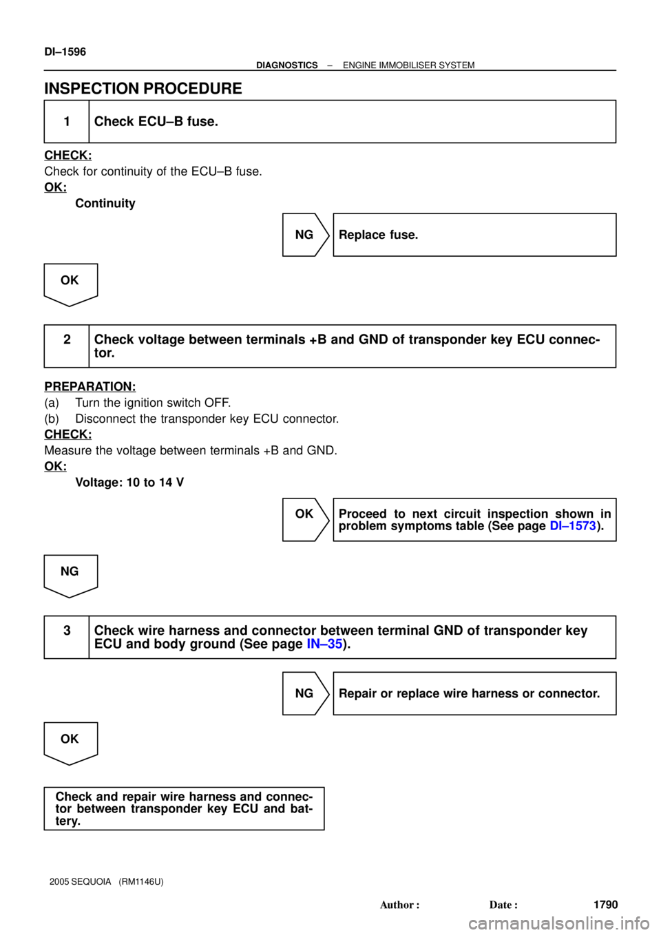
INSPECTION PROCEDURE
1 Check ECU±B fuse.
CHECK:
Check for continuity of the ECU±B fuse.
OK:
Continuity
NG Replace fuse.
OK
2 Check voltage between terminals +B and GND of transponder key ECU connec-
tor.
PREPARATION:
(a) Turn the ignition switch OFF.
(b) Disconnect the transponder key ECU connector.
CHECK:
Measure the voltage between terminals +B and GND.
OK:
Voltage: 10 to 14 V
OK Proceed to next circuit inspection shown in
problem symptoms table (See page DI±1573).
NG
3 Check wire harness and connector between terminal GND of transponder key
ECU and body ground (See page IN±35).
NG Repair or replace wire harness or connector.
OK
Check and repair wire harness and connec-
tor between transponder key ECU and bat-
tery.