Page 1830 of 4323
DID8Y±01
DI±1628
± DIAGNOSTICSCOMBINATION METER SYSTEM
1822 Author�: Date�:
2005 SEQUOIA (RM1146U)
CIRCUIT INSPECTION
Entire combination meter does not operate
CIRCUIT DESCRIPTION
This is the power source circuit of the combination meter.
The combination meter uses BEAN to determine that the ignition switch is in the ACC position or not.
The ST terminal (C5±3) is used as an auxiliary power source to prevent voltage drop when the ignition switch
is ON. When the ST terminal circuit is open or shorted, the combination meter illumination may flicker when
cranking the engine.
Page 1833 of 4323
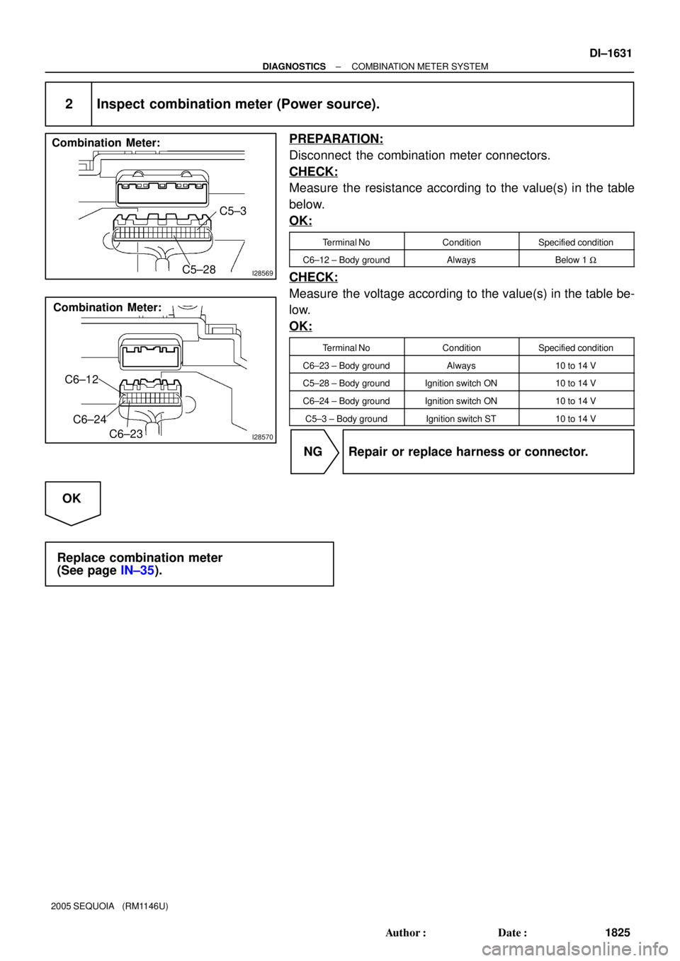
I28569
C5±3
C5±28
Combination Meter:
I28570
C6±12
C6±24
C6±23
Combination Meter:
± DIAGNOSTICSCOMBINATION METER SYSTEM
DI±1631
1825 Author�: Date�:
2005 SEQUOIA (RM1146U)
2 Inspect combination meter (Power source).
PREPARATION:
Disconnect the combination meter connectors.
CHECK:
Measure the resistance according to the value(s) in the table
below.
OK:
Terminal NoConditionSpecified condition
C6±12 ± Body groundAlwaysBelow 1 W
CHECK:
Measure the voltage according to the value(s) in the table be-
low.
OK:
Terminal NoConditionSpecified condition
C6±23 ± Body groundAlways10 to 14 V
C5±28 ± Body groundIgnition switch ON10 to 14 V
C6±24 ± Body groundIgnition switch ON10 to 14 V
C5±3 ± Body groundIgnition switch ST10 to 14 V
NG Repair or replace harness or connector.
OK
Replace combination meter
(See page IN±35).
Page 1836 of 4323
N02332
1
2 3
DI±1634
± DIAGNOSTICSCOMBINATION METER SYSTEM
1828 Author�: Date�:
2005 SEQUOIA (RM1146U)
3 Inspect vehicle speed sensor.
PREPARATION:
(a) Disconnect the vehicle speed sensor connector.
(b) Connect the positive (+) lead from the battery to terminal
1 and the negative (±) lead to terminal 2.
(c) Connect the positive (+) lead from the tester to terminal
3 and the negative (±) lead to terminal 2.
(d) Rotate the shaft.
CHECK:
Check that voltage between terminals 2 and 3 changes from
approx. 0 V to16 V or more.
OK:
Voltage changes from approx. 0 V to 16 V
HINT:
The voltage should change 4 times for every revolution of the
speed sensor shaft.
NG Replace vehicle speed sensor.
OK
Page 1840 of 4323
I28571
C5±23
Combination Meter:
I28567
GND
DI±1638
± DIAGNOSTICSCOMBINATION METER SYSTEM
1832 Author�: Date�:
2005 SEQUOIA (RM1146U)
3 Inspect combination meter.
PREPARATION:
(a) Check the input signal waveform.
(1) Remove the combination meter with the connectors
connected.
(2) Connect the oscilloscope to terminal C5±23 and
body ground.
(3) Start the engine.
CHECK:
Check signal waveform according to the condition(s) in the
table below.
ItemCondition
Tool setting5 V/DIV, 10 ms/DIV
Vehicle conditionEngine idle speed
OK:
Waveform appears as shown in the illustration.
HINT:
As engine speed increases, the cycle of the signal waveform
narrows.
OK Replace combination meter
(See page IN±35).
NG
Page 1844 of 4323
I28574
F
Float
E
321
DI±1642
± DIAGNOSTICSCOMBINATION METER SYSTEM
1836 Author�: Date�:
2005 SEQUOIA (RM1146U)
3 Inspect fuel receiver gauge.
PREPARATION:
Remove the fuel sender gauge assy.
CHECK:
(a) Measure the resistance between terminals 2 and 3 of the
connector according to the value(s) in the table below.
OK:
Float levelSpecified condition
F3 to 5 W
E107.5 to 112.5 W
NG Replace fuel sender gauge.
OK
Page 1849 of 4323

INSPECTION PROCEDURE
1 Read value of hand±held tester")
I28577
Wire Harness Connector
Front View:
R6
IG
T
E
± DIAGNOSTICSCOMBINATION METER SYSTEM
DI±1647
1841 Author�: Date�:
2005 SEQUOIA (RM1146U)
INSPECTION PROCEDURE
1 Read value of hand±held tester.
PREPARATION:
(a) Connect the hand±held tester to the DLC3.
(b) Turn the ignition switch ON, and push the hand±held tester main switch ON.
CHECK:
Operate the hand±held tester according to the steps on the display and select ºDATA LISTº.
METER:
ItemMeasurement Item /
Range (Display)Normal ConditionDiagnostic Note
LIGHT RHEOSTATLight Control Rheostat /
Min.: 0 Max.: 255Light control rheostat switch is
Dark (0) " Bright (255)
OK:
Light brightness can be changed within the specified range by manual operation.
OK Replace combination meter.
(See page IN±35)
NG
2 Check harness and connector (Power source circuit).
PREPARATION:
Disconnect the R6 light control rheostat switch connector.
CHECK:
Measure the resistance according to the value(s) in the table
below.
OK:
Terminal No. (Symbol)ConditionSpecified condition
R6±5 (E) ± Body groundAlwaysBelow 1 W
CHECK:
Measure the voltage according to the value(s) in the table be-
low.
OK:
Terminal No. (Symbol)ConditionSpecified condition
R6±4 (T) ± Body groundLight control switch
TAIL or HEAD10 to 14 V
R6±1 (IG) ± Body groundIgnition switch ON10 to 14 V
NG Repair or replace harness or connector.
OK
Page 1854 of 4323
I28578
w/o Power Seat:
B16
ON
OFF
I28579
w/ Power Seat:
B16
ON
OFF
DI±1652
± DIAGNOSTICSCOMBINATION METER SYSTEM
1846 Author�: Date�:
2005 SEQUOIA (RM1146U)
2 Inspect front seat inner belt (Driver side).
PREPARATION:
Disconnect the connector from the front seat inner belt assy
(Driver Side).
CHECK:
Measure the resistance according to the value(s) in the table
below.
OK:
Terminal No.ConditionSpecified condition
(*1) B16±3 ± B16±13Seat belt is fastened10 kW or higher
(*1) B16±3 ± B16±13Seat belt is unfastenedBelow 1 W
(*2) B16±2 ± B16±3Seat belt is fastened10 kW or higher
(*2) B16±2 ± B16±3Seat belt is unfastenedBelow 1 W
*1: w/o Power Seat
*2: w/ Power Seat
NG Replace front seat inner belt (Driver side).
OK
Page 1858 of 4323

2 Read value of hand±held tester.
PREPARATION:
(a) Connect the hand±held tester to the DLC3.
(b)")
I01278
DI±1656
± DIAGNOSTICSCOMBINATION METER SYSTEM
1850 Author�: Date�:
2005 SEQUOIA (RM1146U)
2 Read value of hand±held tester.
PREPARATION:
(a) Connect the hand±held tester to the DLC3.
(b) Turn the ignition switch ON, and push the hand±held tester main switch ON.
CHECK:
Operate the hand±held tester according to the steps on the display and select ºDATA LISTº.
METER:
ItemMeasurement Item /
Range (Display)Normal ConditionDiagnostic Note
OIL GAUGEOil Gauge /
Min.: 0 Max.: 255Tester indication changes accord-
ing to the oil pressure receiver
gauge angle.
OK:
Oil pressure displayed on the tester is almost the same as the actual oil pressure.
OK Replace combination meter.
(See page IN±35)
NG
3 Inspect oil pressure sender gauge.
PREPARATION:
Disconnect the connector from the oil pressure sender.
CHECK:
(a) Check that no continuity exists between the terminal and
ground with the engine stopped.
(b) Check that continuity exists between the terminal and
ground with the engine running.
HINT:
Oil pressure should be over 24.5 kPa (0.25 kgf/cm
2, 3.55 psi).
OK:
When engine is stopped:
No continuity
When engine is running:
Continuity
NG Replace oil pressure sender gauge.
OK