Page 1902 of 4323
DI94S±08
DI±1700
± DIAGNOSTICSBODY CONTROL SYSTEM
1894 Author�: Date�:
2005 SEQUOIA (RM1146U)
CIRCUIT INSPECTION
Power source circuit
CIRCUIT DESCRIPTION
This circuit provides power to operate the body ECU.
BDR terminal: Power source for door lock motor
S+B terminal: Power source for security horn
ACC terminal: Power source for accessory
BECU terminal: Power source for backing up body ECU
IG terminal: Power source for starting body ECU
WIG terminal: Power source for washer motor
Page 1904 of 4323
DI±1702
± DIAGNOSTICSBODY CONTROL SYSTEM
1896 Author�: Date�:
2005 SEQUOIA (RM1146U)
INSPECTION PROCEDURE
1 Check RAD No. 2, AM1, WSH, ECU±IG, Door No. 2 and ECU±B fuses.
CHECK:
Check for continuity of the RAD No. 2, AM1, WSH, ECU±IG, door No. 2 and ECU±B fuses.
OK:
Continuity
NG Replace defective fuse.
OK
2 Check voltage between terminals ACC, WIG, IG, BECU, S+B, BDR and GND1 of
body ECU connector.
PREPARATION:
Turn the ignition switch ON.
CHECK:
Measure the voltage between terminals ACC, WIG, IG and GND1.
OK:
Voltage: 10 to 14 V
PREPARATION:
Turn the ignition switch OFF.
CHECK:
Measure the voltage between terminals BECU, BDR, S+B and GND1.
OK:
Voltage: 10 to 14 V
OK Proceed to next circuit inspection shown in
problem symptoms table (See page DI±1686).
NG
Page 1906 of 4323
I18741
Body ECU
RWW R1
Rear Washer
Motor
C10
Rear
Wiper and
Washer
SwitchRWLS
RWC1 Y±B G±B L±O
L±O
WASH1
OFF
INT
ON
WASH2
J8 J/C1
2
IEIA14
B7
13
AG±B
G±B IL1
B5 10
6 25 10
12
7
2
W±B
WR EW C1R+1R
B5 DI±1704
± DIAGNOSTICSBODY CONTROL SYSTEM
1898 Author�: Date�:
2005 SEQUOIA (RM1146U)
Rear wiper switch and motor circuit
CIRCUIT DESCRIPTION
Body ECU judges the switch position with the terminal voltage of the rear wiper and washer switch and runs
the washer motor.
WIRING DIAGRAM
DI56X±09
Page 1912 of 4323
I28516
J5
J/CBody ECU
FFOG J50
J/C J3
J/C
5 Instrument Panel J/B
From DIMMER Relay (*1) FOG LIGHT Relay
FOG
1K7
1B9
1J10 1L1
3
1 2 D
D
D
1
2F2
Front Fog
Light RH
W±B
B 1
2P
W±B
EDIGALTF10
FL Block 8
5
B
BatteryR±W
C8 Combination Switch
� Fog Light Switch
B613
G±B
10
LFG BFG 11 P
F1
Front Fog
Light LH
G±W (*1)
Y±R (*2) WP
A
(*1): w/ Daytime Running Light
(*2): w/o Daytime Running LightB
J2
J/C B
BW±B
J18
J/C W±B W±B
IL1
From Headlight (*2) 16
A DI±1710
± DIAGNOSTICSBODY CONTROL SYSTEM
1904 Author�: Date�:
2005 SEQUOIA (RM1146U)
Front fog light relay and switch circuit
CIRCUIT DESCRIPTION
The fog light switch is built into the combination switch.
Turning the fog light switch ON supplies power to terminal FFOG of the body ECU.
The fog lights come on when the FOG light relay is turned on.
WIRING DIAGRAM
DI6U4±14
Page 1928 of 4323

2 (±)
DI±1726
± DIAGNOSTICSBODY CONTROL SYSTEM
1920 Author�: Date�:
2005 SEQUOIA (RM1146U)
INSPECTION PROCEDURE
HINT:
When using the hand±held tester, start the inspection from step")
I00298
1 (+)
2 (±)
DI±1726
± DIAGNOSTICSBODY CONTROL SYSTEM
1920 Author�: Date�:
2005 SEQUOIA (RM1146U)
INSPECTION PROCEDURE
HINT:
When using the hand±held tester, start the inspection from step 1 and when not using the hand±held tester,
start from step 2.
1 Check engine hood courtesy switch using hand±held tester.
PREPARATION:
(a) Connect the hand±held tester to the DLC3.
(b) Turn the ignition switch ON.
CHECK:
According to the display on the tester, read the ºDATA LISTº.
BODY ECU:
ItemMeasurement Item/Display
(Range)Normal ConditionDiagnostic Note
HOOD COURTSY SWHood courtesy switch/ON or OFF
ON: Engine hood OPEN
(Hood courtesy switch ON)
OFF: Engine hood CLOSE
(Hood courtesy switch OFF)
±
OK:
The indication on the tester switches between ON and OFF in accordance with the engine hood
courtesy switch status.
OK Proceed to next circuit inspection shown in
problem symptoms table (See page DI±1686).
NG
2 Check engine hood courtesy switch.
PREPARATION:
Disconnect the engine hood courtesy switch connector.
CHECK:
Check continuity between terminals 1 and 2 when the engine
hood lock is locked and unlocked.
OK:
Engine hood lock
conditionTester connectionSpecified condition
LOCK1 ± 2No continuity
UNLOCK1 ± 2Continuity
NG Replace engine hood courtesy switch.
OK
Page 1940 of 4323
DI±1738
± DIAGNOSTICSBODY CONTROL SYSTEM
1932 Author�: Date�:
2005 SEQUOIA (RM1146U)
INSPECTION PROCEDURE
1 Check that DTC B1242 is not indicated (See page DI±1829).
OK:
DTC B1242 is not indicated.
NG Go to multiplex communication system
(See page DI±1892).
OK
2 Check wire harness and connector (PRG circuit).
PREPARATION:
Disconnect the connectors of the wireless door lock receiver and body ECU.
CHECK:
Check continuity between terminal W2±3 (PRG) of the wireless door lock receiver and terminal B5±5 (PRG)
of the body ECU.
OK:
Continuity
NG Repair or replace wire harness or connector.
OK
3 Check voltage between terminals +B and E of wireless door lock receiver.
CHECK:
Measure the voltage between terminals W2±5 (+B) and W2±1 (E) of the wireless door lock receiver.
OK:
Voltage: 10 to 14 V
NG Repair or replace harness or connector.
OK
Page 1941 of 4323

4 Check wireless door lock receiver.
PREPARATION:
Check that malfunction disappears when another wireless door")
± DIAGNOSTICSBODY CONTROL SYSTEM
DI±1739
1933 Author�: Date�:
2005 SEQUOIA (RM1146U)
4 Check wireless door lock receiver.
PREPARATION:
Check that malfunction disappears when another wireless door lock receiver in good condition is installed.
CHECK:
Check wireless door lock function.
OK:
The wireless door lock system operates normally.
NG Proceed to next circuit inspection shown in
problem symptoms table (See page DI±1686).
OK
Failure of the original wireless door lock re-
ceiver.
5 Check wire harness and connector (RDA circuit).
PREPARATION:
Disconnect the wireless door lock receiver connector.
CHECK:
Check continuity between terminal W2±2 (RDA) of the wireless door lock receiver and terminal B5±4 (RDA)
of the body ECU.
OK:
Continuity
NG Repair or replace harness or connector.
OK
6 Check voltage between terminals +B and E of wireless door lock receiver.
CHECK:
Measure the voltage between terminals W2±5 (+B) and W2±1 (E) of the wireless door lock receiver.
OK:
Voltage: 10 to 14 V
NG Repair or replace harness or connector.
OK
Page 1951 of 4323
± DIAGNOSTICSBODY CONTROL SYSTEM
DI±1749
1943 Author�: Date�:
2005 SEQUOIA (RM1146U)
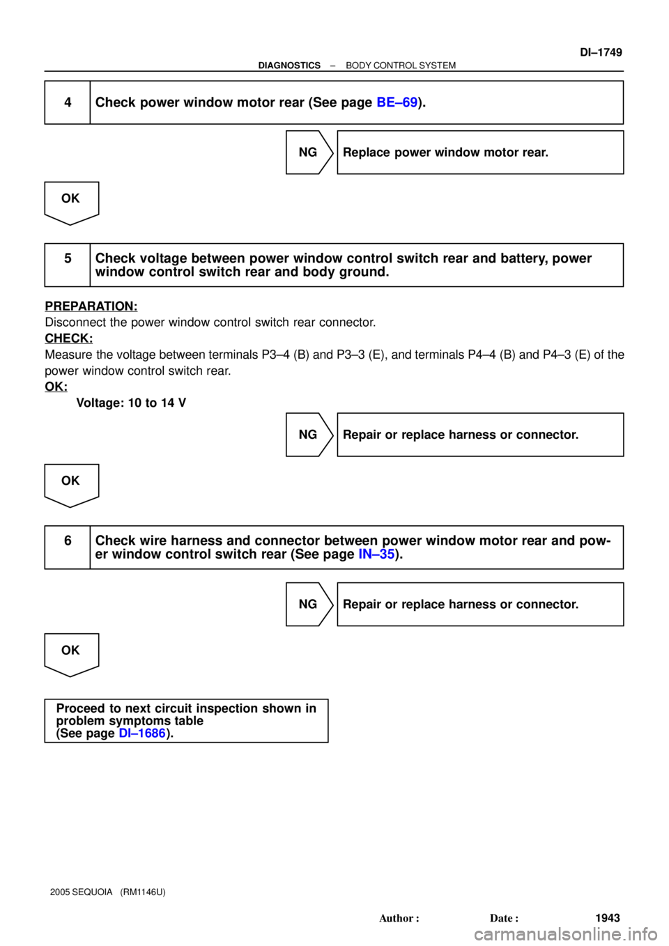
4 Check power window motor rear (See page BE±69).
NG Replace power window motor rear.
OK
5 Check voltage between power window control switch rear and battery, power
window control switch rear and body ground.
PREPARATION:
Disconnect the power window control switch rear connector.
CHECK:
Measure the voltage between terminals P3±4 (B) and P3±3 (E), and terminals P4±4 (B) and P4±3 (E) of the
power window control switch rear.
OK:
Voltage: 10 to 14 V
NG Repair or replace harness or connector.
OK
6 Check wire harness and connector between power window motor rear and pow-
er window control switch rear (See page IN±35).
NG Repair or replace harness or connector.
OK
Proceed to next circuit inspection shown in
problem symptoms table
(See page DI±1686).


 FOG LIGHT Relay
FOG
1K7
1B9
1J10 1L1
3
1 2 D
D
D
1
2F2
Front Fog
Light RH
W±B
B 1
2P
W±B
EDIGALTF10
FL Block 8")