Page 1800 of 4323
I24836
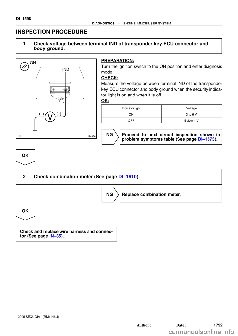
ON
IND
(±) (+)
DI±1598
± DIAGNOSTICSENGINE IMMOBILISER SYSTEM
1792 Author�: Date�:
2005 SEQUOIA (RM1146U)
INSPECTION PROCEDURE
1 Check voltage between terminal IND of transponder key ECU connector and
body ground.
PREPARATION:
Turn the ignition switch to the ON position and enter diagnosis
mode.
CHECK:
Measure the voltage between terminal IND of the transponder
key ECU connector and body ground when the security indica-
tor light is on and when it is off.
OK:
Indicator lightVoltage
ON3 to 6 V
OFFBelow 1 V
NG Proceed to next circuit inspection shown in
problem symptoms table (See page DI±1573).
OK
2 Check combination meter (See page DI±1610).
NG Replace combination meter.
OK
Check and replace wire harness and connec-
tor (See page IN±35).
Page 1802 of 4323
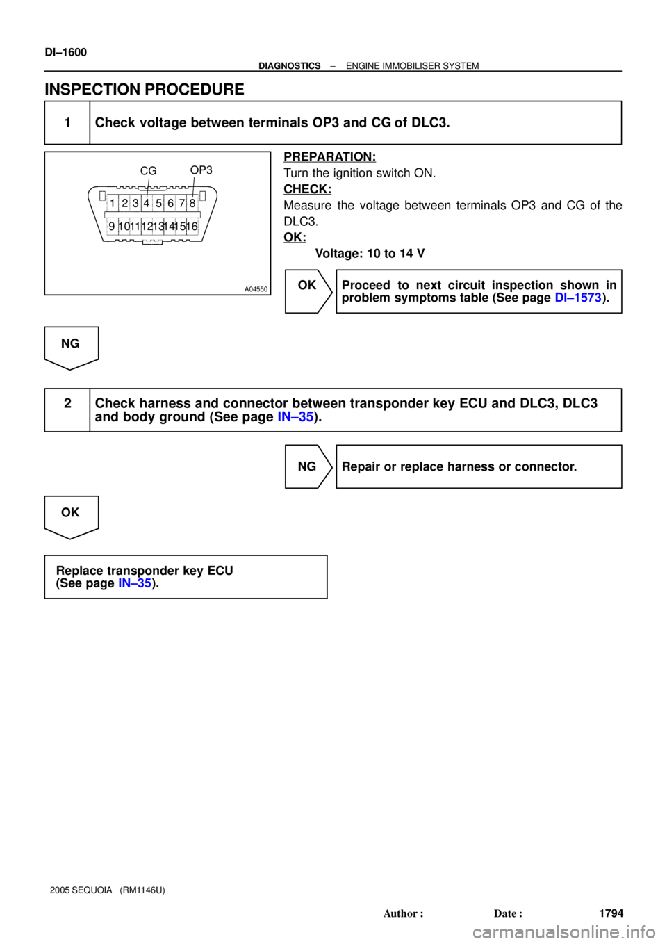
A04550
CGOP3
1 234 5 678
91011 13 151612 14
DI±1600
± DIAGNOSTICSENGINE IMMOBILISER SYSTEM
1794 Author�: Date�:
2005 SEQUOIA (RM1146U)
INSPECTION PROCEDURE
1 Check voltage between terminals OP3 and CG of DLC3.
PREPARATION:
Turn the ignition switch ON.
CHECK:
Measure the voltage between terminals OP3 and CG of the
DLC3.
OK:
Voltage: 10 to 14 V
OK Proceed to next circuit inspection shown in
problem symptoms table (See page DI±1573).
NG
2 Check harness and connector between transponder key ECU and DLC3, DLC3
and body ground (See page IN±35).
NG Repair or replace harness or connector.
OK
Replace transponder key ECU
(See page IN±35).
Page 1803 of 4323
DID8N±01
± DIAGNOSTICSCOMBINATION METER SYSTEM
DI±1601
1795 Author�: Date�:
2005 SEQUOIA (RM1146U)
COMBINATION METER SYSTEM
PRECAUTION
NOTICE:
When disconnecting the battery terminal, initialize the following system after the terminal is recon-
nected.
System NameSee Page
Back Door Power Window Control SystemBE±77
Page 1810 of 4323

SYSTEM DESCRIPTION
1. METER GAUGE AND WARNING/INDICATOR
GAUGE:
ItemDetail
SpeedometerVehicle spe")
DID8Q±01
DI±1608
± DIAGNOSTICSCOMBINATION METER SYSTEM
1802 Author�: Date�:
2005 SEQUOIA (RM1146U)
SYSTEM DESCRIPTION
1. METER GAUGE AND WARNING/INDICATOR
GAUGE:
ItemDetail
SpeedometerVehicle speed sensor (Direct line).
TachometerECM transmits engine speed to the meter to display.
ODO/TRIP MeterCombination meter assy.
FuelDisplays a fuel level according to a signal from the fuel sender gauge (Direct line).
Water TemperatureDisplays engine coolant temperature according to a signal from the ECM (BEAN).
Oil PressureReceives a signal from the oil pressure sender (Direct line).
Volt MeterDisplays vehicle voltage according to a voltage from the IG terminal (Direct line).
WARNING/INDICATOR:
HINT:
Combination meter bulb check is performed for 3 seconds after the ignition switch is turned ON.
ItemDetailList of indicators available for
bulb check
O/D OFFReceives a signal from the ECM (Direct line)±
TURNTurns signal switch ON (Direct line)±
BEAMReceives a signal from the body ECU (*1), Displays a signal received from the
dimmer switch (*2) (Direct line)±
SECURITYReceives a set signal from the transponder key ECU and body ECU (Direct line)±
CHARGEReceives a malfunction signal from the alternator (Direct line)�
AIR BAGReceives a malfunction signal from the airbag sensor center (Direct line)�
D SEAT BELTReceives the driver seat belt signal (Unfastened) from the seat belt inner front LH
(Direct line)±
DOOROpen door indicator comes on when a signal is received from the ECU (BEAN)
from each door±
A/T OIL TEMP.Warning is displayed when the oil temperature is high (Direct line)�
BRAKEComes on when the parking brake switch is on or the brake fluid level warning
switch is on (Direct line)�
MIL (CHECK ENGINE)Receives a malfunction signal from the ECM (Direct line)�
FUEL WARNINGReceives the fuel empty signal from the fuel sender gauge (Direct line)±
ABSReceives a malfunction signal from the skid control ECU (Direct line)�
WASHERWarning is displayed when the washer level is low (Direct line)±
CRUISEReceives a CRUISE on signal or malfunction signal from the ECM (Direct line)±
VSC TRACReceives a malfunction signal from the skid control ECU (Direct line)�
VSC (TRAC) OFFReceives a malfunction signal from the translate ECU (Direct line)�
SLIPReceives a malfunction signal from the translate ECU (Direct line)�
4HIReceives a 4HI signal from the 4WD control ECU (Direct line)±
CTR DIF LOCKReceives a DIF LOCK signal from the 4WD control ECU (Direct line)±
A/T PReceives a P signal from the park/neutral position switch (Direct line)±
A/T NReceives an N signal from the park/neutral position switch (Direct line)±
A/T DReceives a D signal from the park/neutral position switch (Direct line)±
A/T 3Receives a 3 signal from the park/neutral position switch (Direct line)±
A/T 2Receives a 2 signal from the park/neutral position switch (Direct line)±
A/T LReceives an L signal from the park/neutral position switch (Direct line)±
Page 1818 of 4323
DID8V±01
I27709
C5C6
DI±1616
± DIAGNOSTICSCOMBINATION METER SYSTEM
1810 Author�: Date�:
2005 SEQUOIA (RM1146U)
TERMINALS OF ECU
COMBINATION METER ASSY
(a) Disconnect the C5 and C6 connectors.
(b) Measure the resistance of each terminal of the wire harness side connector.
Standard:
Terminals No.Wiring ColorTerminal DescriptionConditionSpecified Condition
C5±5 ± Body groundL±W ± Body
groundCompass and garage
door openerAlwaysBelow 1 W
C5±6 ± Body groundL±R ± Body
groundCompass and garage
door opener communica-
tion line
AlwaysBelow 1 W
C5±30 (*2) ± Body groundW ± Body groundMultiplex communication
signalAlwaysBelow 1 W
C5±31 ± Body groundLG±R ± Body
groundMultiplex communication
signalAlwaysBelow 1 W
C5±32 ± Body groundLG±B ± Body
groundMultiplex communication
signalAlwaysBelow 1 W
Page 1819 of 4323

(c) Reconnect the C5 and C6 connectors.
(d) Measure the voltage of each terminal of the wire harness side")
± DIAGNOSTICSCOMBINATION METER SYSTEM
DI±1617
1811 Author�: Date�:
2005 SEQUOIA (RM1146U)
(c) Reconnect the C5 and C6 connectors.
(d) Measure the voltage of each terminal of the wire harness side connector.
Standard:
Terminals No.Wiring ColorTerminal DescriptionConditionSpecified Condition
C5±1 ± Body groundR±B ± Body
groundParking brake signalParking brake warning light ON6.7 to 12 V
C5±1 ± Body groundR±B ± Body
groundParking brake signalParking brake warning light OFFBelow 1 V
C5±2 ± Body groundLG±R ± Body
groundCRUISE signalCRUISE indicator light ONBelow 1 V
C5±2 ± Body groundLG±R ± Body
groundCRUISE signalCRUISE indicator light OFF10 to 14 V
C5±3 ± Body groundB ± Body groundIgnition switch signal
(Start)Ignition switch OFFBelow 1 V
C5±3 ± Body groundB ± Body groundIgnition switch signal
(Start)Ignition switch START10 to 14 V
C5±4 ± Body groundG±Y ± Body
groundSeat belt condition signal
(Driver side)D±BELT indicator light ONBelow 1 V
C5±4 ± Body groundG±Y ± Body
groundSeat belt condition signal
(Driver side)D±BELT indicator light OFF10 to 14 V
C5±13 ± Body groundLG±R ± Body
groundWasher level signalWASH LVL indicator light ONBelow 1 V
C5±13 ± Body groundLG±R ± Body
groundWasher level signalWASH LVL indicator light OFF10 to 14 V
C5±14 ± Body groundL±O ± Body
groundO/D OFF indicator signalO/D OFF indicator light ONBelow 1 V
C5±14 ± Body groundL±O ± Body
groundO/D OFF indicator signalO/D OFF indicator light OFF10 to 14 V
C5±15 (*1) ± Body groundY±R ± Body
groundA/T oil temperature signalA/T OIL TEMP. warning light ONBelow 1 V
C5±15 (*1) ± Body groundY±R ± Body
groundA/T oil temperature signalA/T OIL TEMP. warning light OFF10 to 14 V
C5±16 ± Body groundLG±B ± Body
groundSecurity indicator light
signal (Engine immobilizer
system)
Security indicator light ON10 to 14 V
C5±16 ± Body groundLG±B ± Body
groundSecurity indicator light
signal (Engine immobilizer
system)
Security indicator light OFFBelow 1 V
C5±17 ± Body groundGR ± Body
groundSecurity indicator light
signal (Theft deterrent
system)
Security indicator light ON10 to 14 V
C5±17 ± Body groundGR ± Body
groundSecurity indicator light
signal (Theft deterrent
system)
Security indicator light OFFBelow 1 V
C5±18 ± Body groundV±W ± Body
groundCHECK ENGINE signalCHECK ENGINE warning light ONBelow 1 V
C5±18 ± Body groundV±W ± Body
groundCHECK ENGINE signalCHECK ENGINE warning light OFF10 to 14 V
C5±19 ± Body groundG±B ± Body
groundA/T shift position signal
(L)A/T L indicator OFFBelow 1 V
Page 1826 of 4323

Wire harness side
1
2
3
4
5
6
13
14
15
16
17
18
19
20
21
22
23
24
25
26
27
28
29
30
31
32
33
34
35
36
37
38
39
401
2
3
4
5
8 6
10
11
12
13
14
15
16
17
18
19
21
23
24
Terminal No.
Translate ECU
ECM
STA Fuse
Front Seat Inner Belt LH (Buckle Switch)
Overhead Module (Garage Door Opener)
Overhead Module (Garage Door Opener)
Washer Level Sensor
ECM
ECM (*1)
Transponder Key Computer
Body ECU
ECM
ECM
Tire Pressure Monitor ECU
Injector No. 1
Light Control Rheostat
ECM
Speed Sensor
4P OUT (Other Parts)
Fuel Sender Gauge
Oil Pressure Sender Gauge
IGN Fuse
Airbag Sensor Assembly
Memory Seat ECU and SW (*2)
Back Door ECU
Integration Control and Panel
Turn Signal Flasher Relay
Park/Neutral Position Switch
Airbag Sensor AssemblyTranslate ECU
Translate ECU
Skid Control ECU
4WD Control ECU
Alternator
Speed Sensor
Fuel Sender Gauge
Ground
Suspension Control ECU
Body ECU (*4)
Body ECU (*3)
Turn Signal Flasher Relay
Skid Control ECU
ECU±B Fuse
IGN1 Fuse Connectors:
Terminal No.
Wire harness side
C5
C64WD Control ECU
4WD Control ECU
Suspension Control ECU
Suspension Control ECU
Suspension Control ECU
*1: 4WD
*2: w/ Driving Position Memory
*3: w/ Daytime Running Light
*4: w/o Daytime Running LightPark/Neutral Position Switch
Park/Neutral Position Switch
Park/Neutral Position Switch
Park/Neutral Position Switch
Park/Neutral Position Switch DI±1624
± DIAGNOSTICSCOMBINATION METER SYSTEM
1818 Author�: Date�:
2005 SEQUOIA (RM1146U)
Page 1827 of 4323

DIAGNOSIS SYSTEM
INSPECT THE DLC3
The vehicles combination meter ECU uses ISO 9141±")
DID8W±01
C00083DLC3
± DIAGNOSTICSCOMBINATION METER SYSTEM
DI±1625
1819 Author�: Date�:
2005 SEQUOIA (RM1146U)
DIAGNOSIS SYSTEM
INSPECT THE DLC3
The vehicle's combination meter ECU uses ISO 9141±2 for
communication. The terminal arrangement of the DLC3 com-
plies with SAE J1962 and matches the ISO 9141±2 format.
Tester connectionConditionSpecified condition
7 (Bus � Line) ± 5 (Signal ground)During communicationPulse generation
4 (Chassis Ground) ± BodyAlwaysBelow 1 W
5 (Signal Ground) ± BodyAlwaysBelow 1 W
16 (B+) ± BodyAlways10 to 14 V
HINT:
If the display shows UNABLE TO CONNECT TO VEHICLE
when you have connected the cable of the hand±held tester to
the DLC3, turned the ignition switch to the ON position and op-
erated the tester, there is a problem either on the vehicle side
or tester side.
�If communication is normal when the tool is connected to
another vehicle, inspect the DLC3 on the original vehicle.
�If communication is still impossible when the tool is con-
nected to another vehicle, the problem is probably in the
tool itself, so consult the Service Department listed in the
tool's instruction manual.