Page 3083 of 4323
± SUSPENSION AND AXLEFRONT LOWER SUSPENSION ARM
SA±79
3075 Author�: Date�:
2005 SEQUOIA (RM1146U)
(c) Replace the No. 2 spring bumper.
(1) Remove the stabilizer bar (See page SA±91).
(2) Using SST, replace the No. 2 spring bumper.
SST 09922±10010
HINT:
At the time of installation, use a torque wrench with a fulcrum
length of 345 mm (13.58 in.).
Torque: 23 N´m (235 kgf´cm, 17 ft´lbf)
(3) Install the stabilizer bar (See page SA±93).
(d) Install the front wheel.
Torque: 110 N´m (1,150 kgf´cm, 83 ft´lbf)
Page 3105 of 4323

SA24B±02
F14284
Socket Wrench
F14286
F14287
SST
SST
F14288
SST
SST
± SUSPENSION AND AXLEREAR AXLE SHAFT
SA±101
3097 Author�: Date�:
2005 SEQUOIA (RM1146U)
REASSEMBLY
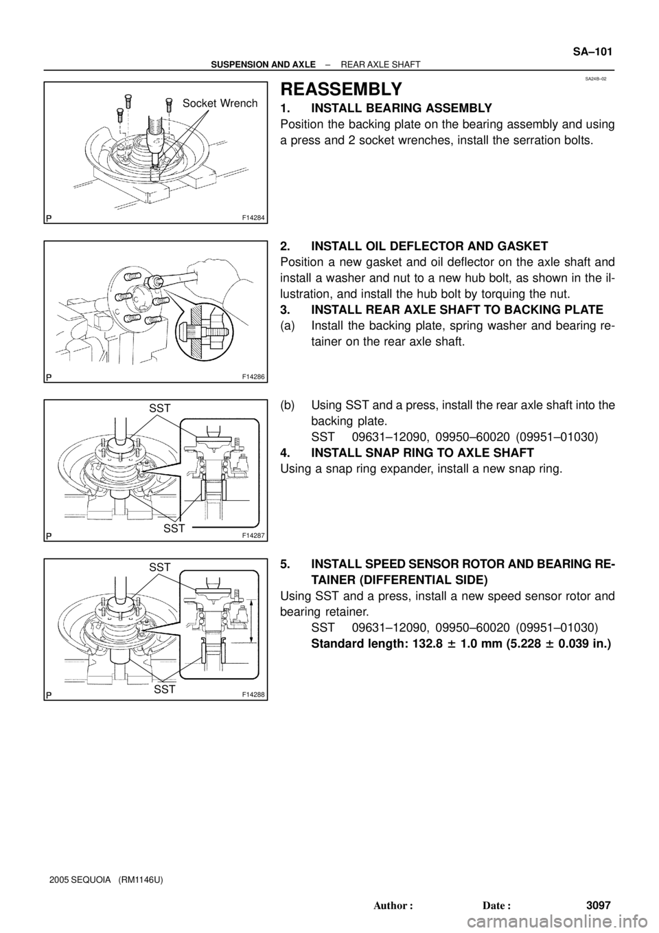
1. INSTALL BEARING ASSEMBLY
Position the backing plate on the bearing assembly and using
a press and 2 socket wrenches, install the serration bolts.
2. INSTALL OIL DEFLECTOR AND GASKET
Position a new gasket and oil deflector on the axle shaft and
install a washer and nut to a new hub bolt, as shown in the il-
lustration, and install the hub bolt by torquing the nut.
3. INSTALL REAR AXLE SHAFT TO BACKING PLATE
(a) Install the backing plate, spring washer and bearing re-
tainer on the rear axle shaft.
(b) Using SST and a press, install the rear axle shaft into the
backing plate.
SST 09631±12090, 09950±60020 (09951±01030)
4. INSTALL SNAP RING TO AXLE SHAFT
Using a snap ring expander, install a new snap ring.
5. INSTALL SPEED SENSOR ROTOR AND BEARING RE-
TAINER (DIFFERENTIAL SIDE)
Using SST and a press, install a new speed sensor rotor and
bearing retainer.
SST 09631±12090, 09950±60020 (09951±01030)
Standard length: 132.8 ± 1.0 mm (5.228 ± 0.039 in.)
Page 3135 of 4323

SA2CX±01
F17148260 mm (10.236 in.)
F16838Clip
Center Pin
Slotted
Hole
± SUSPENSION AND AXLEREAR PNEUMATIC CYLINDER
SA±131
3127 Author�: Date�:
2005 SEQUOIA (RM1146U)
REMOVAL
NOTICE:
�Do not extend the pneumatic cylinder by itself. If the
cylinder is fully extended, it cannot be reused.
�Do not replenish the pneumatic cylinder by itself with
air.
�Do not remove the pneumatic cylinder with air in it.
�If reusing the pneumatic cylinder, replace the 2 O±
rings, plate and connector No.2 with new ones.
�When installing the pneumatic cylinder, keep the cyl-
inder length 260 mm (10.236 in.) or less.
1. BLEED AIR (See page SA±153)
HINT:
Disconnect the one touch air connector of the height control
valve and bleed the air.
2. REMOVE REAR PNEUMATIC CYLINDER
(a) Jack up the vehicle and support the frame with safety
stands.
NOTICE:
�Do the work with the rear axle assy lowered.
�Do the work with the shock absorber installed.
(b) Disconnect the height control tube.
(c) Remove the clip on the upper side of the rear pneumatic
cylinder.
HINT:
�If the clip cannot be easily removed, thread a wire through
the hole to pull it.
�When installing the clip, make sure that the center pin on
the upper side of the rear pneumatic cylinder is in the
slotted hole of the frame.
(d) Remove the rear pneumatic cylinder.
Page 3164 of 4323
F16827
A
A SA±160
± SUSPENSION AND AXLEELECTRONIC MODULATED AIR SUSPENSION
3156 Author�: Date�:
2005 SEQUOIA (RM1146U)
(f) Check that the lengths of the screw parts, ºAº in the il-
lustration, are within the standard values.
Standard length: 6.5 to 15.0 mm (0.26 to 0.59 in.)
(g) Change the vehicle height. (From the normal position to
the high position, and from the high position to the normal
position)
(h) Measure the vehicle height (C ± D measurement) on the
right side and left side.
(i) Check if the vehicle height (C ± D measurement) is within
the specified range.
HINT:
If the values are outside the standard, perform the procedures
from (d) to (i) again.
Page 3181 of 4323

F07754
Pedal Height Push Rod
BR107±04
R00085
Pedal Free Play BR±6
± BRAKEBRAKE PEDAL
3173 Author�: Date�:
2005 SEQUOIA (RM1146U)
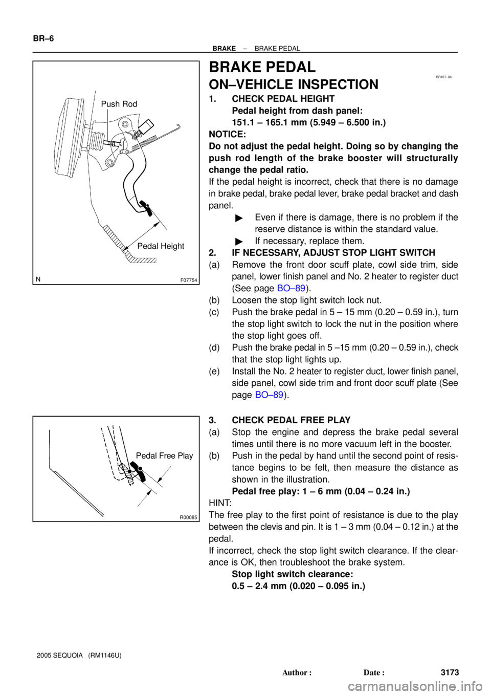
BRAKE PEDAL
ON±VEHICLE INSPECTION
1. CHECK PEDAL HEIGHT
Pedal height from dash panel:
151.1 ± 165.1 mm (5.949 ± 6.500 in.)
NOTICE:
Do not adjust the pedal height. Doing so by changing the
push rod length of the brake booster will structurally
change the pedal ratio.
If the pedal height is incorrect, check that there is no damage
in brake pedal, brake pedal lever, brake pedal bracket and dash
panel.
�Even if there is damage, there is no problem if the
reserve distance is within the standard value.
�If necessary, replace them.
2. IF NECESSARY, ADJUST STOP LIGHT SWITCH
(a) Remove the front door scuff plate, cowl side trim, side
panel, lower finish panel and No. 2 heater to register duct
(See page BO±89).
(b) Loosen the stop light switch lock nut.
(c) Push the brake pedal in 5 ± 15 mm (0.20 ± 0.59 in.), turn
the stop light switch to lock the nut in the position where
the stop light goes off.
(d) Push the brake pedal in 5 ±15 mm (0.20 ± 0.59 in.), check
that the stop light lights up.
(e) Install the No. 2 heater to register duct, lower finish panel,
side panel, cowl side trim and front door scuff plate (See
page BO±89).
3. CHECK PEDAL FREE PLAY
(a) Stop the engine and depress the brake pedal several
times until there is no more vacuum left in the booster.
(b) Push in the pedal by hand until the second point of resis-
tance begins to be felt, then measure the distance as
shown in the illustration.
Pedal free play: 1 ± 6 mm (0.04 ± 0.24 in.)
HINT:
The free play to the first point of resistance is due to the play
between the clevis and pin. It is 1 ± 3 mm (0.04 ± 0.12 in.) at the
pedal.
If incorrect, check the stop light switch clearance. If the clear-
ance is OK, then troubleshoot the brake system.
Stop light switch clearance:
0.5 ± 2.4 mm (0.020 ± 0.095 in.)
Page 3246 of 4323

F16017
Steering Column
Upper Cover
New Marked
Line
Steering Wheel
R00429
Marked Line
F16018
± STEERINGSTEERING WHEEL
SR±11
3238 Author�: Date�:
2005 SEQUOIA (RM1146U)
(d) Turn the steering wheel to its straight position.
HINT:
Refer to the upper surface of the steering wheel, steering spoke
and SRS airbag line for the straight position.
(e) Draw a new line on the masking tape of the steering wheel
as shown in the illustration.
(f) Measure the distance between the 2 lines on the masking
tape of the steering wheel.
(g) Convert the measured distance to steering angle.
Measured distance 1 mm (0.04 in.) = Steering angle
approximately 1 deg.
HINT:
Make a note of the steering angle.
2. ADJUST STEERING ANGLE
(a) Draw a line on the RH and LH tie rod and rack ends where
it can easily be seen.
(b) Using a paper gauge, measure the distance from RH and
LH tie rod ends to the rack end screws.
HINT:
�Measure the RH side and LH side.
�Make a note of the measured values.
(c) Remove the RH and LH boot clips from the rack boots.
(d) Loosen the RH and LH lock nuts.
(e) Turn the RH and LH rack end by the same amount (but
in different directions) according to the steering angle.
1 turn 360 deg. of rack end (1.5 mm (0.059 in.) horizon-
tal movement) = 12 deg. of steering angle
(f) Tighten the RH and LH lock nuts.
Torque: 55 N´m (560 kgf´cm, 41 ft´lbf)
NOTICE:
Make sure that the difference in length between RH and LH
tie rod ends and rack end screws are within 1.5 mm (0.059
in.).
(g) Install the RH and LH boot clips.
Page 3253 of 4323

F06734
Plate Washer A
Plate Washer BSST
Screw
R12472
SST
Retaining Ring SR±18
± STEERINGTILT STEERING COLUMN
3245 Author�: Date�:
2005 SEQUOIA (RM1146U)
9. REMOVE STEERING COLUMN HOUSING WITH MAIN
SHAFT ASSEMBLY
(a) Set SST, 2 plate washers (18 and 36 mm outer diameter)
and a screw (4.0 mm diameter, 0.7 mm pitch, 15.0 mm
length), as shown in the illustration. Then remove the 2
pivot pins.
SST 09910±00015 (09911±00011, 09912±00010)
Reference
Plate washer A (18 mm): 90562±04012
Plate washer B (36 mm): 90201±10201
Screw: 90154±40015
(b) Remove the column housing with the shaft assembly from
the column tube assembly.
NOTICE:
Do not bend the universal joint of the main shaft assembly
more than 15°.
(c) Remove the tilt spring and spring guide.
10. REMOVE 2 TILT NO. 1 STOPPERS
11. REMOVE MAIN SHAFT STOPPER
12. REMOVE MAIN SHAFT ASSEMBLY
(a) Install SST to the main shaft assembly, as shown in the
illustration.
SST 09612±07010
(b) Using SST, compress the compression spring.
SST 09612±07010
NOTICE:
Do not bend the universal joint of the shaft assembly more
than 15°.
HINT:
Hold the shaft assembly with your hand to prevent rotation.
(c) Using a screwdriver, remove the No. 2 steering column
ring.
(d) Remove the spring retainer, compression spring, upper
bearing inner race seat and inner race.
13. REMOVE TILT LEVER
Remove the tilt lever lock shaft and shift lever.
Page 3265 of 4323
SR0RF±05
F06719
Vane Pump Shaft
Front HousingBushing
N00372
HeightThickness
Length
R10282
Feeler Gauge
SR±30
± STEERINGPOWER STEERING VANE PUMP
3257 Author�: Date�:
2005 SEQUOIA (RM1146U)
INSPECTION
1. CHECK OIL CLEARANCE BETWEEN VANE PUMP
SHAFT AND BUSHING
Using a micrometer and caliper gauge, measure the oil clear-
ance.
Standard clearance:
0.03 to 0.05 mm (0.0012 to 0.0020 in.)
Maximum clearance: 0.07 mm (0.0028 in.)
If it is more than the maximum, replace the shaft and front hous-
ing.
2. INSPECT VANE PUMP ROTOR AND VANE PLATES
(a) Using a micrometer, measure the height, thickness and
length of the 10 plates.
Minimum height: 8.6 mm (0.339 in.)
Minimum thickness: 1.397 mm (0.0550 in.)
Minimum length: 14.991 mm (0.5902 in.)
(b) Using a feeler gauge, measure the clearance between
the rotor groove and plate.
Maximum clearance: 0.033 mm (0.0013 in.)