Page 2638 of 4323
EM0801
EM0281
A05912
EM2011
± ENGINE MECHANICALCYLINDER HEAD
EM±51
2630 Author�: Date�:
2005 SEQUOIA (RM1146U)
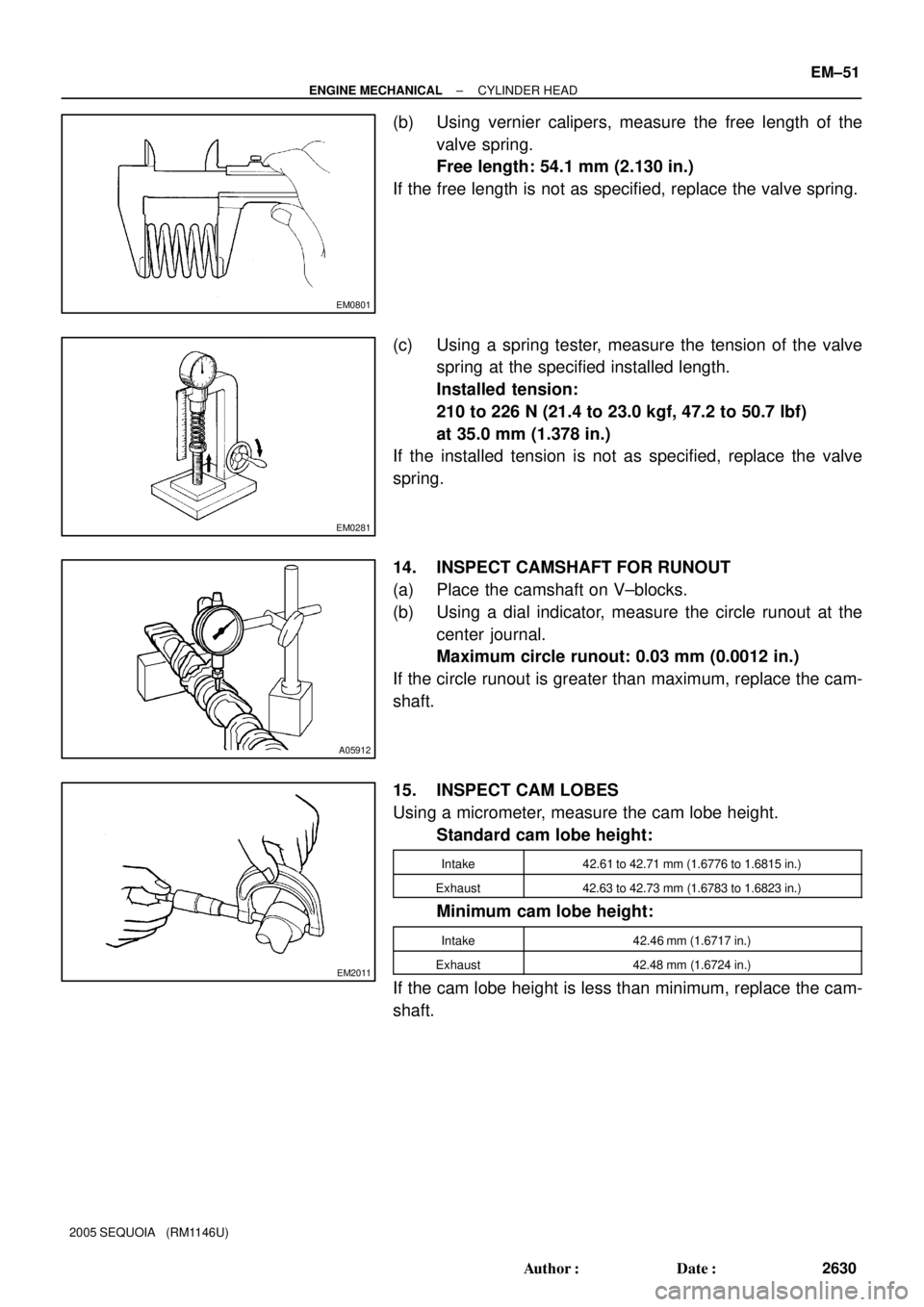
(b) Using vernier calipers, measure the free length of the
valve spring.
Free length: 54.1 mm (2.130 in.)
If the free length is not as specified, replace the valve spring.
(c) Using a spring tester, measure the tension of the valve
spring at the specified installed length.
Installed tension:
210 to 226 N (21.4 to 23.0 kgf, 47.2 to 50.7 lbf)
at 35.0 mm (1.378 in.)
If the installed tension is not as specified, replace the valve
spring.
14. INSPECT CAMSHAFT FOR RUNOUT
(a) Place the camshaft on V±blocks.
(b) Using a dial indicator, measure the circle runout at the
center journal.
Maximum circle runout: 0.03 mm (0.0012 in.)
If the circle runout is greater than maximum, replace the cam-
shaft.
15. INSPECT CAM LOBES
Using a micrometer, measure the cam lobe height.
Standard cam lobe height:
Intake42.61 to 42.71 mm (1.6776 to 1.6815 in.)
Exhaust42.63 to 42.73 mm (1.6783 to 1.6823 in.)
Minimum cam lobe height:
Intake42.46 mm (1.6717 in.)
Exhaust42.48 mm (1.6724 in.)
If the cam lobe height is less than minimum, replace the cam-
shaft.
Page 2653 of 4323
A23357
Push
A23337
A
B
C
D
E A
BC
D E
E
EE
EEE
EEEE
EE
A23337
1
4
22
8
9 2
321
6 10
17
18
5
71314
19121115
1620
A23335
Service Bolt EM±66
± ENGINE MECHANICALCYLINDER HEAD
2645 Author�: Date�:
2005 SEQUOIA (RM1146U)
(9) Push in the camshaft oil seal.
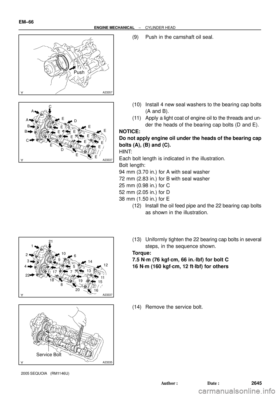
(10) Install 4 new seal washers to the bearing cap bolts
(A and B).
(11) Apply a light coat of engine oil to the threads and un-
der the heads of the bearing cap bolts (D and E).
NOTICE:
Do not apply engine oil under the heads of the bearing cap
bolts (A), (B) and (C).
HINT:
Each bolt length is indicated in the illustration.
Bolt length:
94 mm (3.70 in.) for A with seal washer
72 mm (2.83 in.) for B with seal washer
25 mm (0.98 in.) for C
52 mm (2.05 in.) for D
38 mm (1.50 in.) for E
(12) Install the oil feed pipe and the 22 bearing cap bolts
as shown in the illustration.
(13) Uniformly tighten the 22 bearing cap bolts in several
steps, in the sequence shown.
Torque:
7.5 N´m (76 kgf´cm, 66 in.´lbf) for bolt C
16 N´m (160 kgf´cm, 12 ft´lbf) for others
(14) Remove the service bolt.
Page 2656 of 4323
A23340
A
B
C
E
EA
B C
EE
E
EE
EE D
E EEE
ED
A23340
1
4
22
82
3 21
6
57
13 141912
11
15
1620
9
1017
18
A23338
Service Bolt
EM7143
Seal Packing
± ENGINE MECHANICALCYLINDER HEAD
EM±69
2648 Author�: Date�:
2005 SEQUOIA (RM1146U)
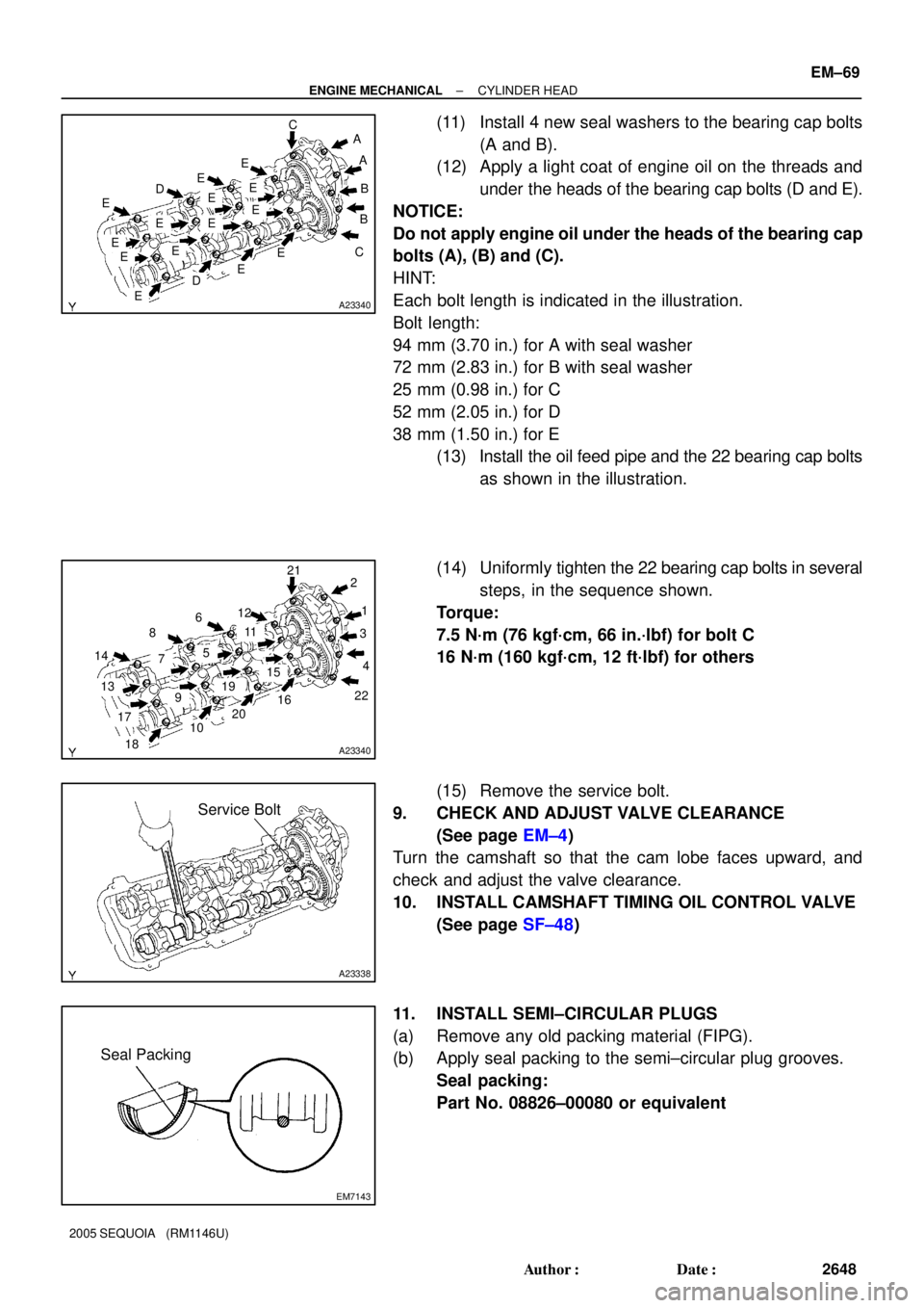
(11) Install 4 new seal washers to the bearing cap bolts
(A and B).
(12) Apply a light coat of engine oil on the threads and
under the heads of the bearing cap bolts (D and E).
NOTICE:
Do not apply engine oil under the heads of the bearing cap
bolts (A), (B) and (C).
HINT:
Each bolt length is indicated in the illustration.
Bolt length:
94 mm (3.70 in.) for A with seal washer
72 mm (2.83 in.) for B with seal washer
25 mm (0.98 in.) for C
52 mm (2.05 in.) for D
38 mm (1.50 in.) for E
(13) Install the oil feed pipe and the 22 bearing cap bolts
as shown in the illustration.
(14) Uniformly tighten the 22 bearing cap bolts in several
steps, in the sequence shown.
Torque:
7.5 N´m (76 kgf´cm, 66 in.´lbf) for bolt C
16 N´m (160 kgf´cm, 12 ft´lbf) for others
(15) Remove the service bolt.
9. CHECK AND ADJUST VALVE CLEARANCE
(See page EM±4)
Turn the camshaft so that the cam lobe faces upward, and
check and adjust the valve clearance.
10. INSTALL CAMSHAFT TIMING OIL CONTROL VALVE
(See page SF±48)
11. INSTALL SEMI±CIRCULAR PLUGS
(a) Remove any old packing material (FIPG).
(b) Apply seal packing to the semi±circular plug grooves.
Seal packing:
Part No. 08826±00080 or equivalent
Page 2745 of 4323
B16499
Fulcrum
Length
30 cm
SST
B02714
CORRECT
WRONG
Delivery Pipe O±Ring
B04939
Delivery
Pipe
Intake
Manifold O±Ring
Grommet
Injector
Insulator
B17532
Quick Type
Disconnect
B11684
Quick Type
Push
Pull
± SFISFI SYSTEM
SF±3
2737 Author�: Date�:
2005 SEQUOIA (RM1146U)
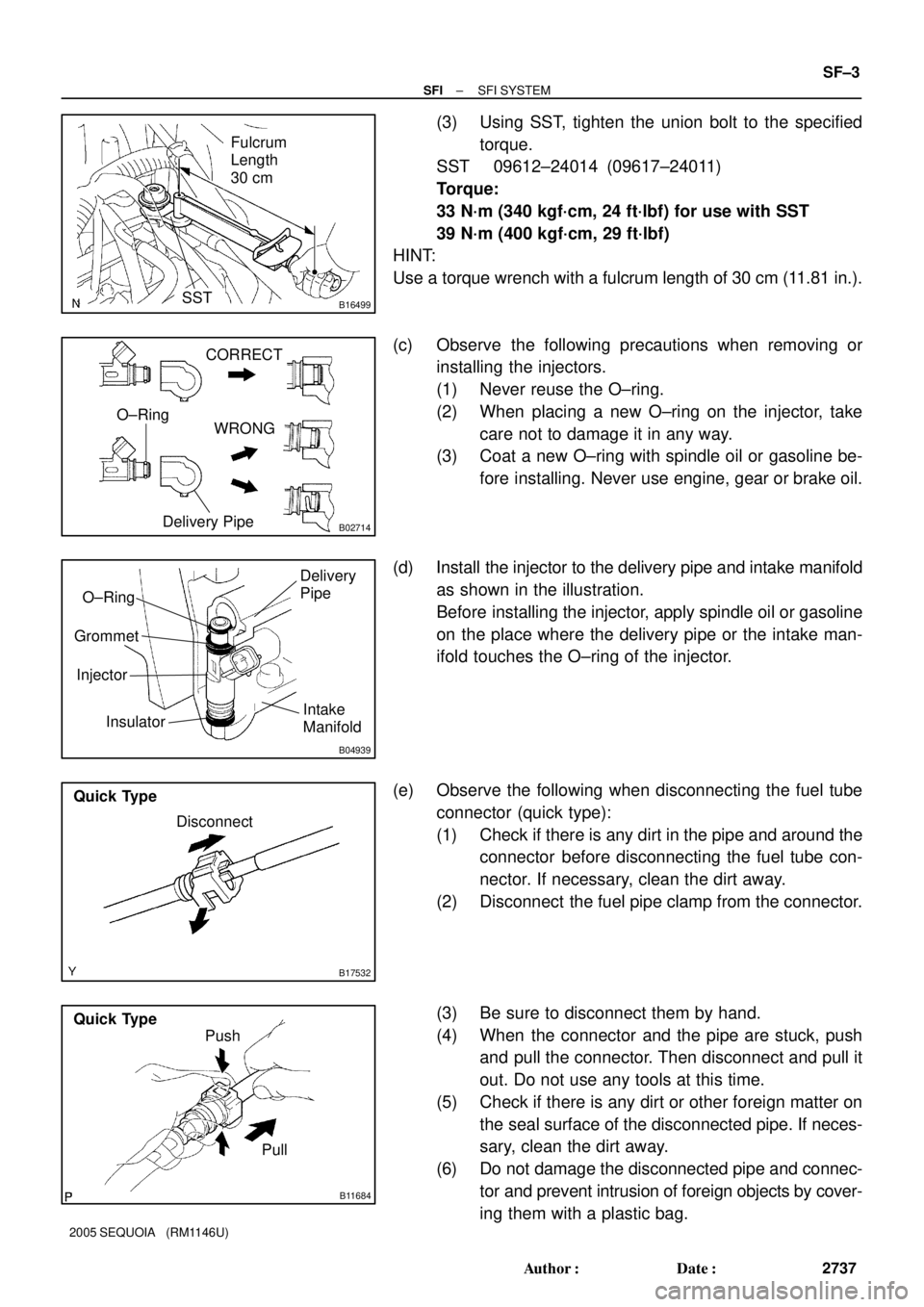
(3) Using SST, tighten the union bolt to the specified
torque.
SST 09612±24014 (09617±24011)
Torque:
33 N´m (340 kgf´cm, 24 ft´lbf) for use with SST
39 N´m (400 kgf´cm, 29 ft´lbf)
HINT:
Use a torque wrench with a fulcrum length of 30 cm (11.81 in.).
(c) Observe the following precautions when removing or
installing the injectors.
(1) Never reuse the O±ring.
(2) When placing a new O±ring on the injector, take
care not to damage it in any way.
(3) Coat a new O±ring with spindle oil or gasoline be-
fore installing. Never use engine, gear or brake oil.
(d) Install the injector to the delivery pipe and intake manifold
as shown in the illustration.
Before installing the injector, apply spindle oil or gasoline
on the place where the delivery pipe or the intake man-
ifold touches the O±ring of the injector.
(e) Observe the following when disconnecting the fuel tube
connector (quick type):
(1) Check if there is any dirt in the pipe and around the
connector before disconnecting the fuel tube con-
nector. If necessary, clean the dirt away.
(2) Disconnect the fuel pipe clamp from the connector.
(3) Be sure to disconnect them by hand.
(4) When the connector and the pipe are stuck, push
and pull the connector. Then disconnect and pull it
out. Do not use any tools at this time.
(5) Check if there is any dirt or other foreign matter on
the seal surface of the disconnected pipe. If neces-
sary, clean the dirt away.
(6) Do not damage the disconnected pipe and connec-
tor and prevent intrusion of foreign objects by cover-
ing them with a plastic bag.
Page 2833 of 4323
B17478
AB
± COOLINGWATER PUMP
CO±9
2825 Author�: Date�:
2005 SEQUOIA (RM1146U)
(f) Install the water inlet and housing assembly with the 2
bolts. Alternately tighten the bolts.
Torque: 18 N´m (185 kgf´cm, 13 ft´lbf)
HINT:
Each bolt length is indicated in the illustration.
Bolt length:
76 mm (3.00 in.) for A
22 mm (0.87 in.) for B
(g) Connect the water bypass hose to the water inlet housing.
3. INSTALL NO.2 IDLER PULLEY (See page EM±23)
4. INSTALL TIMING BELT (See page EM±23)
5. FILL WITH ENGINE COOLANT
6. START ENGINE AND CHECK FOR ENGINE COOLANT
LEAKS
7. RECHECK ENGINE COOLANT LEVEL
Page 2844 of 4323
LU0GW±07
B07231
B07232
SST
LU±2
± LUBRICATIONOIL AND FILTER
2836 Author�: Date�:
2005 SEQUOIA (RM1146U)
REPLACEMENT
CAUTION:
�Prolonged and repeated contact with mineral oil will
result in the removal of natural fats from the skin,
leading to dryness, irritation and dermatitis. In addi-
tion, used engine oil contains potentially harmful
contaminants which may cause skin cancer.
�Care should be taken, therefore, when changing en-
gine oil to minimize the frequency and length of time
your skin is exposed to used engine oil. Protective
clothing and gloves that cannot be penetrated by oil
should be worn. The skin should be thoroughly
washed with soap and water, or use water±less hand
cleaner, to remove any used engine oil. Do not use
gasoline, thinners, or solvents.
�In order to preserve the environment, used oil and
used oil filters must be disposed of only at desig-
nated disposal sites.
1. w/ Oil filter change:
REMOVE ENGINE UNDER COVER
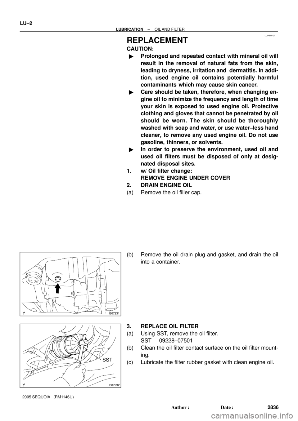
2. DRAIN ENGINE OIL
(a) Remove the oil filler cap.
(b) Remove the oil drain plug and gasket, and drain the oil
into a container.
3. REPLACE OIL FILTER
(a) Using SST, remove the oil filter.
SST 09228±07501
(b) Clean the oil filter contact surface on the oil filter mount-
ing.
(c) Lubricate the filter rubber gasket with clean engine oil.
Page 2858 of 4323
B05842
B13061
A
B
Seal Width
2 - 3 mm A
B LU-16
- LUBRICATIONOIL PUMP
2850 Author�: Date�:
2005 SEQUOIA (RM1146U)
HINT:
�Use a 6 mm hexagon wrench for the hexagon head bolt.
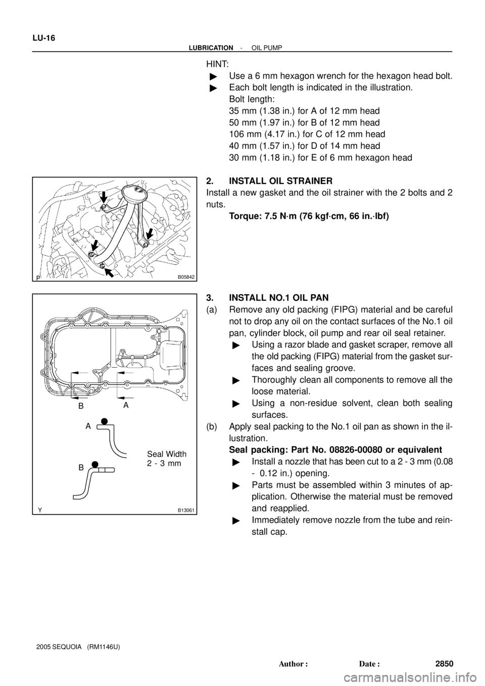
�Each bolt length is indicated in the illustration.
Bolt length:
35 mm (1.38 in.) for A of 12 mm head
50 mm (1.97 in.) for B of 12 mm head
106 mm (4.17 in.) for C of 12 mm head
40 mm (1.57 in.) for D of 14 mm head
30 mm (1.18 in.) for E of 6 mm hexagon head
2. INSTALL OIL STRAINER
Install a new gasket and the oil strainer with the 2 bolts and 2
nuts.
Torque: 7.5 N´m (76 kgf´cm, 66 in.´lbf)
3. INSTALL NO.1 OIL PAN
(a) Remove any old packing (FIPG) material and be careful
not to drop any oil on the contact surfaces of the No.1 oil
pan, cylinder block, oil pump and rear oil seal retainer.
�Using a razor blade and gasket scraper, remove all
the old packing (FIPG) material from the gasket sur-
faces and sealing groove.
�Thoroughly clean all components to remove all the
loose material.
�Using a non-residue solvent, clean both sealing
surfaces.
(b) Apply seal packing to the No.1 oil pan as shown in the il-
lustration.
Seal packing: Part No. 08826-00080 or equivalent
�Install a nozzle that has been cut to a 2 - 3 mm (0.08
- 0.12 in.) opening.
�Parts must be assembled within 3 minutes of ap-
plication. Otherwise the material must be removed
and reapplied.
�Immediately remove nozzle from the tube and rein-
stall cap.
Page 2859 of 4323
B07335
A
B
A
A
A
BBBC
BBBB
C
CC
D
D
B05839
B05845
AB
Seal Width
2 - 3 mm A
B
- LUBRICATIONOIL PUMP
LU-17
2851 Author�: Date�:
2005 SEQUOIA (RM1146U)
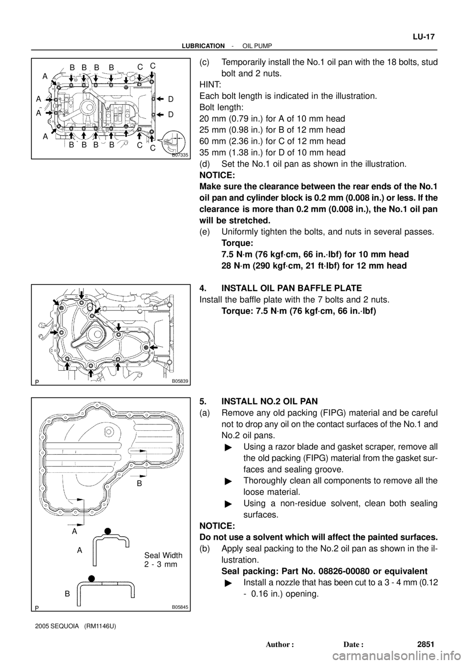
(c) Temporarily install the No.1 oil pan with the 18 bolts, stud
bolt and 2 nuts.
HINT:
Each bolt length is indicated in the illustration.
Bolt length:
20 mm (0.79 in.) for A of 10 mm head
25 mm (0.98 in.) for B of 12 mm head
60 mm (2.36 in.) for C of 12 mm head
35 mm (1.38 in.) for D of 10 mm head
(d) Set the No.1 oil pan as shown in the illustration.
NOTICE:
Make sure the clearance between the rear ends of the No.1
oil pan and cylinder block is 0.2 mm (0.008 in.) or less. If the
clearance is more than 0.2 mm (0.008 in.), the No.1 oil pan
will be stretched.
(e) Uniformly tighten the bolts, and nuts in several passes.
Torque:
7.5 N´m (76 kgf´cm, 66 in.´lbf) for 10 mm head
28 N´m (290 kgf´cm, 21 ft´lbf) for 12 mm head
4. INSTALL OIL PAN BAFFLE PLATE
Install the baffle plate with the 7 bolts and 2 nuts.
Torque: 7.5 N´m (76 kgf´cm, 66 in.´lbf)
5. INSTALL NO.2 OIL PAN
(a) Remove any old packing (FIPG) material and be careful
not to drop any oil on the contact surfaces of the No.1 and
No.2 oil pans.
�Using a razor blade and gasket scraper, remove all
the old packing (FIPG) material from the gasket sur-
faces and sealing groove.
�Thoroughly clean all components to remove all the
loose material.
�Using a non-residue solvent, clean both sealing
surfaces.
NOTICE:
Do not use a solvent which will affect the painted surfaces.
(b) Apply seal packing to the No.2 oil pan as shown in the il-
lustration.
Seal packing: Part No. 08826-00080 or equivalent
�Install a nozzle that has been cut to a 3 - 4 mm (0.12
- 0.16 in.) opening.