Page 2891 of 4323

P10588
Ohmmeter
Continuity
P00299
OhmmeterContinuity
S02267
Ohmmeter(B)
(A)
Z00037
ST0019
± STARTINGSTARTER
ST±9
2883 Author�: Date�:
2005 SEQUOIA (RM1146U)
7. INSPECT FIELD COIL FOR OPEN CIRCUIT
Using an ohmmeter, check that there is continuity between the
lead wire and field coil brush lead.
If there is no continuity, replace the field frame.
8. INSPECT SHUNT COIL FOR OPEN CIRCUIT
Using an ohmmeter, check that there is continuity between the
field coil end and field frame.
If there is no continuity, repair or replace the field frame.
9. INSPECT SHUNT COIL FOR OPEN CIRCUIT
Using an ohmmeter, measure the resistance between shunt
coil terminals (A) and (B).
Resistance: 1.5 to 1.9 W at 20 °C (68 °F)
If the resistance is not as specified, replace the field frame.
10. INSPECT BRUSH LENGTH
Using vernier calipers, measure the brush length.
Standard length: 15.0 mm (0.591 in. )
Minimum length: 9.0 mm (0.354 in. )
If the length is less than minimum, replace the brush holder and
field frame.
11. INSPECT BRUSH SPRING LOAD
Using a pull scale, measure the spring load by pulling the spring
from the brush until they are separated.
Standard spring installed load: 21.5 to 27.5 N ( 2.2 to
2.8 kgf, 4.8 to 6.2 lbf )
Minimum installed load: 12.7 N (1.3 kgf, 2.9 lbf )
If the installed load is less than minimum, replace the brush
springs.
Page 2910 of 4323

CH0M0±02
B12264
Ohmmeter
Continuity
B12265
Ohmmeter
No Continuity
B12266
B16374
Length CH±10
± CHARGINGGENERATOR
2902 Author�: Date�:
2005 SEQUOIA (RM1146U)
INSPECTION
1. INSPECT ROTOR
(a) Check the rotor for open circuit.
Using an ohmmeter, check that there is continuity be-
tween the slip rings.
Standard resistance: 1.5 to 1.9 W at 20°C (68°F)
If there is no continuity, replace the rotor.
(b) Check the rotor for ground.
Using an ohmmeter, check that there is no continuity be-
tween the slip ring and rotor.
If there is continuity, replace the rotor.
(c) Check that the slip rings are not rough or scored.
If rough or scored, replace the rotor.
(d) Using vernier calipers, measure the slip ring diameter.
Standard diameter: 14.2 to 14.4 mm (0.559 to 0.567 in.)
Minimum diameter: 14.0 mm (0.551 in.)
If the diameter is less than the minimum, replace the rotor.
2. INSPECT BRUSHES
Using vernier caliper, measure the exposed brush length.
Standard exposed length: 10.5 mm (0.413 in.)
Minimum exposed length: 4.5 mm (0.177 in.)
If the exposed length is less than the minimum, replace the
brushes and the brush holder assembly.
3. INSPECT BEARING
Check the bearing is not rough or worn.
If necessary, replace the bearing (See page CH±11).
Page 2923 of 4323

D13867
AT134±01
D12704
Orange
Blue
Clamp
ClampBolt
Bolt
D12739
D12704
Orange
Blue
Clamp
Clamp
A B
± AUTOMATIC TRANSMISSION (A750E, A750F)ATF TEMPERATURE SENSOR
AT±7
2915 Author�: Date�:
2005 SEQUOIA (RM1146U)
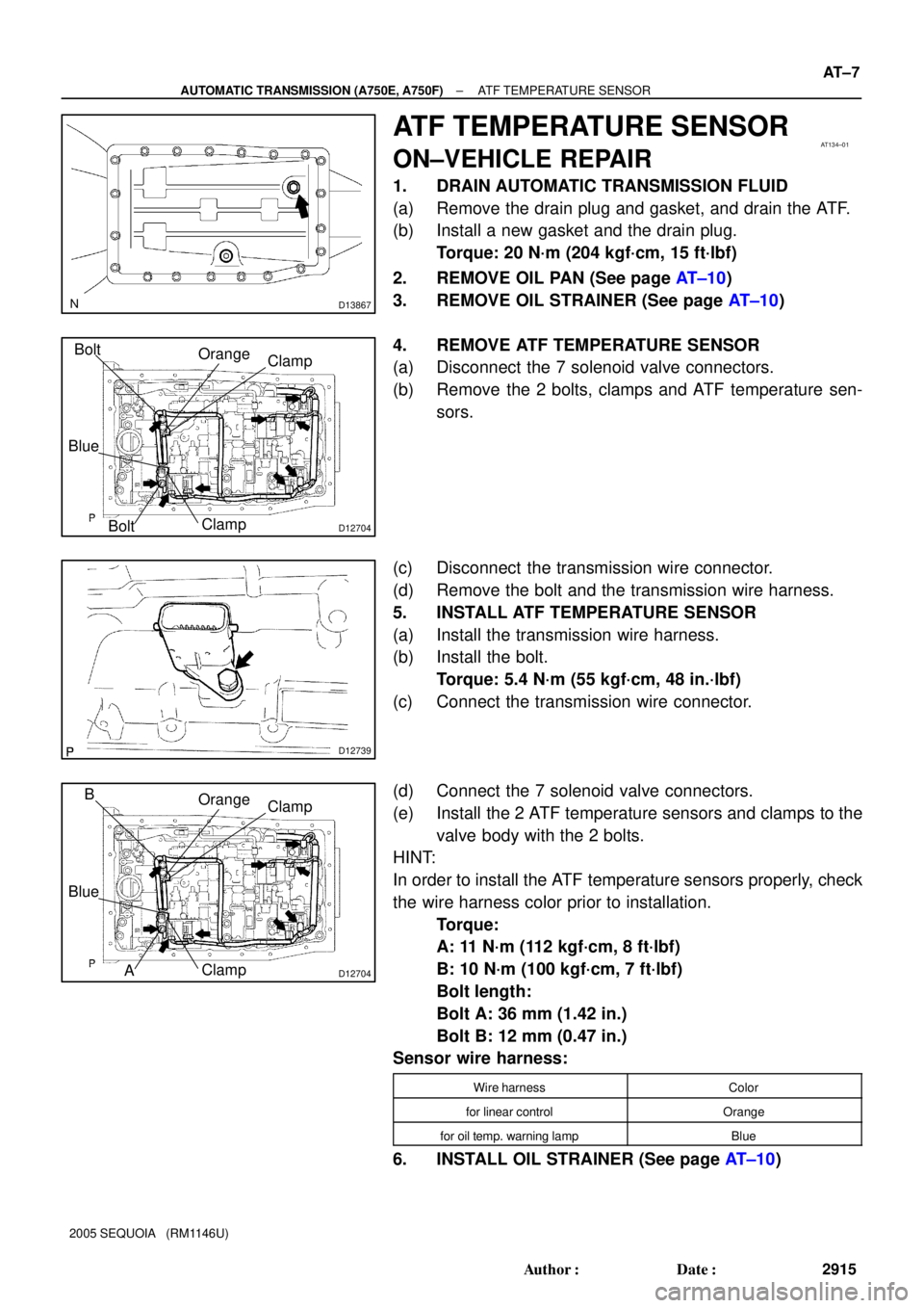
ATF TEMPERATURE SENSOR
ON±VEHICLE REPAIR
1. DRAIN AUTOMATIC TRANSMISSION FLUID
(a) Remove the drain plug and gasket, and drain the ATF.
(b) Install a new gasket and the drain plug.
Torque: 20 N´m (204 kgf´cm, 15 ft´lbf)
2. REMOVE OIL PAN (See page AT±10)
3. REMOVE OIL STRAINER (See page AT±10)
4. REMOVE ATF TEMPERATURE SENSOR
(a) Disconnect the 7 solenoid valve connectors.
(b) Remove the 2 bolts, clamps and ATF temperature sen-
sors.
(c) Disconnect the transmission wire connector.
(d) Remove the bolt and the transmission wire harness.
5. INSTALL ATF TEMPERATURE SENSOR
(a) Install the transmission wire harness.
(b) Install the bolt.
Torque: 5.4 N´m (55 kgf´cm, 48 in.´lbf)
(c) Connect the transmission wire connector.
(d) Connect the 7 solenoid valve connectors.
(e) Install the 2 ATF temperature sensors and clamps to the
valve body with the 2 bolts.
HINT:
In order to install the ATF temperature sensors properly, check
the wire harness color prior to installation.
Torque:
A: 11 N´m (112 kgf´cm, 8 ft´lbf)
B: 10 N´m (100 kgf´cm, 7 ft´lbf)
Bolt length:
Bolt A: 36 mm (1.42 in.)
Bolt B: 12 mm (0.47 in.)
Sensor wire harness:
Wire harnessColor
for linear controlOrange
for oil temp. warning lampBlue
6. INSTALL OIL STRAINER (See page AT±10)
Page 2928 of 4323

D12705
D12704
Orange
Blue
Clamp
Clamp
A B
D12703
D13866
AT±12
± AUTOMATIC TRANSMISSION (A750E, A750F)VALVE BODY ASSEMBLY
2920 Author�: Date�:
2005 SEQUOIA (RM1146U)
(b) Install the 19 bolts and the valve body.
Torque: 11 N´m (112 kgf´cm, 8 ft´lbf)
Bolt length:
Bolt A: 25 mm (0.98 in.)
Bolt B: 36 mm (1.42 in.)
10. INSTALL TEMPERATURE SENSOR
(a) Connect the 7 solenoid valve connectors.
(b) Install the 2 temperature sensors and clamps to the valve
body with the 2 bolts.
HINT:
In order to install the ATF temperature sensors properly, check
the wire harness color prior to installation.
Torque:
A: 11 N´m (112 kgf´cm, 8 ft´lbf)
B: 10 N´m (100 kgf´cm, 7 ft´lbf)
Bolt length:
Bolt A: 36 mm (1.42 in.)
Bolt B: 12 mm (0.47 in.)
Sensor wire harness:
Wire harnessColor
for linear controlOrange
for oil temp. warning lampBlue
11. INSTALL OIL STRAINER
(a) Install a new O±ring.
(b) Install the oil strainer with the 4 bolts.
Torque: 10 N´m (100 kgf´cm, 7 ft´lbf)
12. INSTALL OIL PAN
HINT:
Remove any packing material, and be careful not to spill oil on
the contacting surfaces of the transmission case and the oil
pan.
Using a new gasket, install the oil pan with the 20 bolts.
Torque: 4.4 N´m (45 kgf´cm, 39 in´lbf)
Page 3013 of 4323

SA3213
AB
Front
C D
R13228
R13229
FA0018
AB
FrontA
B
A: Inside
B: Outside
± SUSPENSION AND AXLEFRONT WHEEL ALIGNMENT
SA±9
3005 Author�: Date�:
2005 SEQUOIA (RM1146U)
5. INSPECT TOE±IN
Toe±in (total):
UCK35L±GKBSKA
Tire size: P245/70R16
Tire size: P265/70R16 and P265/65R17
Tire size: P265/65R17 (*1)
UCK35L±GKBLKA
UCK45L±GKBSKA
Tire size: P265/70R16 (*1)
UCK45L±GKBLKA
A + B: 0°05' ± 0°09' (0.09° ± 0.15°)
C ± D: 1.19 ± 2 mm (0.05 ± 0.08 in.)
A + B: 0°05' ± 0°09' (0.09° ± 0.15°)
C ± D: 1.29 ± 2 mm (0.05 ± 0.08 in.)
A + B: 0°05' ± 0°09' (0.09° ± 0.15°)
C ± D: 1.28 ± 2 mm (0.05 ± 0.08 in.)
A + B: 0°05' ± 0°09' (0.08° ± 0.15°)
C ± D: 1.15 ± 2 mm (0.05 ± 0.08 in.)
A + B: 0°05' ± 0°09' (0.08° ± 0.15°)
C ± D: 1.08 ± 2 mm (0.04 ± 0.08 in.)
A + B: 0°05' ± 0°09' (0.08° ± 0.15°)
C ± D: 1.07 ± 2 mm (0.04 ± 0.08 in.)
A + B: 0°04' ± 0°09' (0.07° ± 0.15°)
C ± D: 0.99 ± 2 mm (0.04 ± 0.08 in.)
(*1): Air suspension models only
If the toe±in is not within the specified values, adjust the rack
ends.
6. ADJUST TOE±IN AND WHEEL ANGLE
(a) Remove the 2 clips.
(b) Loosen the tie rod end lock nuts.
(c) Turn the right and left rack ends by an equal amount to
adjust the toe±in.
HINT:
Try to adjust the toe±in to the center of the specified values.
(d) Make sure that the lengths of the right and left rack ends
are the same.
Rack end length difference: 1.5 mm (0.059 in.) or less
(e) Tighten the tie rod end lock nuts.
Torque: 55 N´m (560 kgf´cm, 41 ft´lbf)
(f) Place the boots on the seats and install the clips.
HINT:
Make sure that the boots are not twisted.
(g) Inspect the wheel angle.
Turn the steering wheel fully and measure the turning
angle.
Page 3014 of 4323
SA±10
± SUSPENSION AND AXLEFRONT WHEEL ALIGNMENT
3006 Author�: Date�:
2005 SEQUOIA (RM1146U)
Wheel turning angle:
ModelInside wheelOutside wheel:
Reference
UCK35L±GKBSKA±35°24'
(-35.40°)32°10' (32.16°)
31°54' (31.90°) (*1)
UCK35L±GKBLKA±35°22'
(-35.36°)32°07' (32.12°)
UCK45L±GKBSKA±35°37'
(-35.61°)32°17' (32.28°)
UCK45L±GKBLKA±35°35'
(-35.59°)32°16' (32.26°)
(*1): Air suspension model with P265/65R17 tire only.
If the right and left wheel turning angles differ from the specified
values, readjust the toe±in and wheel angle to within the speci-
fied values. At this time, make sure that the lengths of the right
and left rack ends are the same.
Rack end length difference: 1.5 mm (0.059 in.) or less
Page 3038 of 4323

SA14H±06
F06649
W03195
Inboard Joint Boot Outboard Joint Boot
Vinyl Tape
W03218
Matchmarks
F06650
SA±34
± SUSPENSION AND AXLEFRONT DRIVE SHAFT
3030 Author�: Date�:
2005 SEQUOIA (RM1146U)
REASSEMBLY
1. INSTALL DUST COVER
Using a screwdriver and hammer, install a new dust cover.
2. INSTALL DUST SEAL
Using a screwdriver and hammer, install a new dust seal.
3. TEMPORARILY INSTALL OUTBOARD AND INBOARD
JOINT BOOTS AND NEW BOOT CLAMPS
HINT:
�Before installing the boots, wrap the spline of the out-
board joint shaft with vinyl tape to prevent the boots from
bearing damaged.
�Before installing the boots, place 3 new clamps to the
small boot ends and large boot end (outboard joint side).
4. INSTALL INBOARD JOINT SHAFT TO OUTBOARD
JOINT SHAFT
Align the matchmarks placed before disassembly, and using a
snap ring expander, put in the inboard joint shaft while expand-
ing the snap ring.
5. INSTALL BOOT TO OUTBOARD JOINT
Before assembling the boot, pack the outboard joint and boot
with grease in the boot kit.
Grease capacity (Color = Black):
205 ± 225 g (7.23 ± 7.94 oz.)
6. INSTALL BOOT TO INBOARD JOINT SHAFT
(a) Pack the inboard joint and boot with grease in the boot kit.
Grease capacity (Color = Black):
190 ± 210 g (6.70 ± 7.41 oz.)
(b) Temporarily install the boot to the inboard joint shaft.
7. CHECK DRIVE SHAFT LENGTH
(a) Make sure that the 2 boots are on the shaft groove.
(b) Make sure that the 2 boots are not stretched or contracted
when the drive shaft is at standard length.
Drive shaft standard length:
523.5 ± 2.0 mm (20.610 ± 0.079 in.)
8. INSTALL LARGE INBOARD JOINT BOOT CLAMP TO
INBOARD JOINT SHAFT BOOT
(a) Place the large inboard joint boot clamp.
Page 3082 of 4323

SA24S±02
W01884
SST
SST
F07275
Mark
Mark
Steel Plate
F07276
MarksSteel Plate
F07277
Removal:
Installation: SA±78
± SUSPENSION AND AXLEFRONT LOWER SUSPENSION ARM
3074 Author�: Date�:
2005 SEQUOIA (RM1146U)
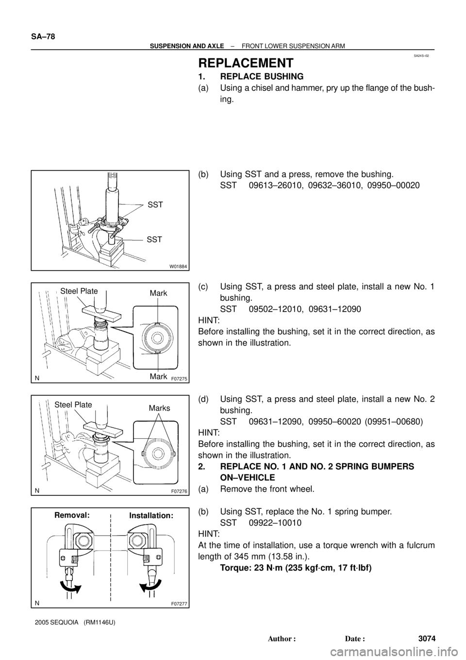
REPLACEMENT
1. REPLACE BUSHING
(a) Using a chisel and hammer, pry up the flange of the bush-
ing.
(b) Using SST and a press, remove the bushing.
SST 09613±26010, 09632±36010, 09950±00020
(c) Using SST, a press and steel plate, install a new No. 1
bushing.
SST 09502±12010, 09631±12090
HINT:
Before installing the bushing, set it in the correct direction, as
shown in the illustration.
(d) Using SST, a press and steel plate, install a new No. 2
bushing.
SST 09631±12090, 09950±60020 (09951±00680)
HINT:
Before installing the bushing, set it in the correct direction, as
shown in the illustration.
2. REPLACE NO. 1 AND NO. 2 SPRING BUMPERS
ON±VEHICLE
(a) Remove the front wheel.
(b) Using SST, replace the No. 1 spring bumper.
SST 09922±10010
HINT:
At the time of installation, use a torque wrench with a fulcrum
length of 345 mm (13.58 in.).
Torque: 23 N´m (235 kgf´cm, 17 ft´lbf)