Page 186 of 4323

STEERING
SERVICE DATA
POWER STEERING FLUID
Oil level rise Maximum5 mm (0.20 in.)
Oil pressure at")
SS08W±04
SS±44
± SERVICE SPECIFICATIONSSTEERING
186 Author�: Date�:
2005 SEQUOIA (RM1146U)
STEERING
SERVICE DATA
POWER STEERING FLUID
Oil level rise Maximum5 mm (0.20 in.)
Oil pressure at idle speed with valve closed Minimum8,336 kPa (85 kgf/cm2, 1,209 psi)
STEERING WHEEL
Steering wheel freeplayMaximum30 mm (1.18 in.)
Steering effort at idle speedReference:4.9 N´m (50 kgf´cm, 43 in.´lbf)
PS VANE PUMP
Pump shaft and front housing bushing oil clearance STD0.03±0.05 mm (0.0012±0.0020 in.)
Pump shaft and front housing bushing oil clearanceMaximum0.07 mm (0.0028 in.)
Vane plate heightMinimum8.6 mm (0.339 in.)
Vane plate thickness Minimum1.397 mm (0.0550 in.)
Vane plate lengthMinimum14.991 mm (0.5902 in.)
Vane plate and pump rotor groove clearanceMaximum0.033 mm (0.0013 in.)
Vane plate length Pump rotor and cam ring mark
None14.999±15.001 mm (0.59051±0.59059 in.)
114.997±14.999 mm (0.59043±0.59051 in.)
214.995±14.997 mm (0.59035±0.59043 in.)
314.993±14.995 mm (0.59027±0.59035 in.)
414.991±14.993 mm (0.59020±0.59027 in.)
Flow control valve spring length Minimum33.2 mm (1.307 in.)
Pump rotating torqueMaximum0.28 N´m (2.8 kgf´cm, 2.4 in.´lbf) or less
PS GEAR
Steering rack runout Maximum0.03 mm (0.0118 in.)
Total preload Turning1.2±1.6 N´m (12±16 kgf´cm, 10.4±13.9 in.´lbf)
Page 230 of 4323
 OX2B (E7±33) ± E2 (E8±28)
R ± G±WIdlingPulse generation
(See waveform 10)
STP (E4 15) E")
A2364720 msec./DIV 20 V/DIV
Ground
DI±36
± DIAGNOSTICSENGINE
230 Author�: Date�:
2005 SEQUOIA (RM1146U) OX2B (E7±33) ± E2 (E8±28)
R ± G±WIdlingPulse generation
(See waveform 10)
STP (E4 15) E1 (E6 1)GY BRBrake pedal is depressed7.5 to 14 VSTP (E4±15) ± E1 (E6±1)G±Y ± BRBrake pedal is releasedBelow 1.5 V
ST1 (E4 16) E1 (E6 1)LB BRBrake pedal is depressedBelow 1.5 VST1± (E4±16) ± E1 (E6±1)L±B ± BRBrake pedal is released7.5 to 14 V
STA (E6±11) ± E1 (E6±1)B±R ± BRShift lever position P or N, Ignition switch START6.0 V or more
STSW (E6±12) ± E1 (E6±1)B ± BRShift lever position P or N, ignition switch START6.0 V or more
STAR/NSW (E7 8) E1 (E6 1)BBRIG switch ON, Other shift position in P, N9 to 14 VSTAR/NSW (E7±8) ± E1 (E6±1)B ± BRIG switch ON, Shift position in P, N0 to 3.0 V
W (E5 30) E1 (E6 1)VW BRIdling9 to 14 VW (E5±30) ± E1 (E6±1)V±W ± BRIG switch ONBelow 3.0 V
TACH (E5±1) ± E1 (E6±1)Y±G ± BRIdlingPulse generation
(See waveform 11)
ACIS (E8±33) ± E1 (E6±1)B±L ± BRIG switch ON9 to 14 V
VPMP (E4±5) ± E1 (E6±1)P±L ± BRIgnition switch ON9 V to 14 V
MPMP (E4±6) ± E1 (E6±1)V±G ± BR�Vacuum pump OFF
�Vacuum pump ON0 V to 3 V
9 V to 14 V
PPMP (E4±22) ± E1 (E6±1)R±G ± BRIgnition switch ON3 V to 3.6 V
AIV1 (E8±27) ± E1 (E6±1)L±B ± BRIgnition switch ON9 to 14 V
AIV2 (E8±26) ± E1 (E6±1)P±L ± BRIgnition switch ON9 to 14 V
AIRV (E4±4) ± E1 (E6±1)R±W ± BRIgnition switch ON9 to 14 V
AIRP (E4±25) ± E1 (E6±1)G±W ± BRIgnition switch ON9 to 14 V
AIP (E8±32) ± E1 (E6±1)B±Y ± BRIgnition switch ON3 V to 3.6 V
*1: The ECM terminal voltage is constant regardless of the output voltage from the sensor.
WAVEFORM 1
Fuel injector
ECM Terminal NamesBetween #10 (to 40) and E01
Tester Ranges20 V/DIV, 20 msec./DIV
ConditionsIdling
HINT:
The wavelength becomes shorter as the engine rpm increases.
Page 231 of 4323
 Ground CH1
(b) Ground CH2
(c) Ground CH3
± DIAGNOSTICSENGINE
DI±37
23")
A23648
GND 1V/ DIV KNK1 Signal Waveform
1 msec./ Division
A23649
200 msec./DIV 5 V/DIV
GroundA
B
A23650
20 msec./DIV 2 V/DIV
(a) Ground CH1
(b) Ground CH2
(c) Ground CH3
± DIAGNOSTICSENGINE
DI±37
231 Author�: Date�:
2005 SEQUOIA (RM1146U)
WAVEFORM 2
Knock sensor
ECM Terminal NameBetween KNK1 and EKNK
Between KNK2 and EKN2
Tester Range1 V/DIV, 1 msec./DIV
ConditionMaintain engine RPM at 2,000 rpm after engine warmed±up
HINT:
�The wavelength becomes shorter as engine rpm in-
creases.
�The waveforms and amplitudes displayed differ slightly
depending on the vehicle.
WAVEFORM 3
VVT OCV
ECM Terminal NameBetween OC1+ and OC1±
Between OC2+ and OC2±
Tester Range0.2 V/DIV, 200 msec./DIV
ConditionAccelerate slowly after engine warmed±up
HINT:
In the DATA LIST, the items VVT OCV DUTY B1 and B2 show
the duty ratio of voltage flowing to the OCV (see illustration on
left).
VVT OCV DUTY B1, B2 = A/B x 100 (%)
WAVEFORM 4
(a) VVT sensor bank 1
(b) VVT sensor bank 2
(c) Crankshaft position sensor
ECM Terminal Name
(a) Between VV1+ and VV1±
(b) Between VV2+ and VV2±
(c) Between NE+ and NE±
Tester Range2 V/DIV, 20 msec./DIV
ConditionIdle after engine warmed±up
HINT:
The wavelength becomes shorter as the engine rpm increases.
Page 232 of 4323

(b)
Ground
Ground
A23652
10 msec./DIV 1 V/DIV
Ground
A23653
1 msec./DIV 5 V/DIV
Ground
A23654
1 msec./DIV 5 V/DIV
Ground
A23655
(a)
(b)
20 msec./DIV 2 V/DIV
Ground
Grou")
A23651
20 msec./DIV 5 V/DIV
(a)
(b)
Ground
Ground
A23652
10 msec./DIV 1 V/DIV
Ground
A23653
1 msec./DIV 5 V/DIV
Ground
A23654
1 msec./DIV 5 V/DIV
Ground
A23655
(a)
(b)
20 msec./DIV 2 V/DIV
Ground
Ground
DI±38
± DIAGNOSTICSENGINE
232 Author�: Date�:
2005 SEQUOIA (RM1146U)
WAVEFORM 5
(a) Camshaft position sensor
(b) Crankshaft position sensor
ECM Terminal Name(a) Between G2+ and G2±
(b) Between NE+ and NE±
Tester Range5 V/DIV, 20 msec./DIV
ConditionIdle after engine warmed±up
HINT:
The wavelength becomes shorter as the engine rpm increases.
WAVEFORM 6
Vehicle speed signal
ECM Terminal NameBetween SP2+ and SP2±
Tester Range5 V/DIV, 10 msec./DIV
ConditionDriving by 40 km/h (25 mph)
HINT:
The wavelength becomes shorter as vehicle speed increases.
WAVEFORM 7
Throttle actuator positive terminal
ECM Terminal NameBetween M+ and ME01
Tester Range5 V/DIV, 1 msec./DIV
ConditionIdle after engine warmed±up
HINT:
The duty ratio varies depending on the throttle opening opera-
tion.
WAVEFORM 8
Throttle actuator negative terminal
ECM Terminal NameBetween M± and ME01
Tester Range5 V/DIV, 1 msec./DIV
ConditionIdle after engine warmed±up
HINT:
The duty ratio varies depending on the throttle opening opera-
tion.
WAVEFORM 9
(a) Igniter IGT signal (from ECM to igniter)
(b) Igniter IGF signal (from igniter to ECM)
ECM Terminal Name(a) Between IGT1 (to IGT8) and E1
(b) Between IGF1 (IGF2) and E1
Tester Range2 V/DIV, 20 msec./DIV
ConditionIdling
HINT:
The wavelength becomes shorter as vehicle speed increases.
Page 233 of 4323
A23656
0.2 V/DIV
200 msec./DIV
Ground
A2365710 msec./DIV 5 V/DIV
Ground
± DIAGNOSTICSENGINE
DI±39
233 Author�: Date�:
2005 SEQUOIA (RM1146U)
WAVEFORM 10
Heated oxygen sensor
ECM Terminal NamesBetween OX1B and E2
Tester Ranges0.2 V/DIV, 200 msec./DIV
ConditionsEngine speed maintained 2,500 rpm for 2 minutes after
warming up sensor
HINT:
In the DATA LIST, item O2S B1S2 shows the ECM input values
from the heated oxygen sensor.
WAVEFORM 11
Engine speed signal
ECM Terminal NamesBetween TACH and E1
Tester Ranges5 V/DIV, 10 msec./DIV
ConditionsIdling
HINT:
The wavelength becomes shorter as vehicle speed increases.
Page 271 of 4323
A02397
OCV Signal Waveform
1 msec./Division5 V/
Division
GND
(A) (A) (A)
B17414ECM ConnectorE6
OC1+
OC1±
OC2+OC2±
E1
± DIAGNOSTICSENGINE
DI±77
271 Author�: Date�:
2005 SEQUOIA (RM1146U)
3 Check voltage between terminals OC1+ and OC1±, OC2+ and OC2± of ECM con-
nector.
CHECK:
(a) Inspection using the oscilloscope.
(b) During idling, check the waveform between the specified
terminals of the E6 ECM connector.
HINT:
The waveform frequency (A) is lengthened as the engine speed
becomes higher.
OK:
Standard:
The correct waveform is as shown.
NG Replace ECM (See page SF±80).
OK
Page 276 of 4323
A02397
OCV Signal Waveform
200 msec./Division5 V/
Division
GND
(A) (A) (A)
B17414ECM ConnectorE6
OC1+
OC1±
OC2+OC2±
E1
B12806
Ohmmeter
DI±82
± DIAGNOSTICSENGINE
276 Author�: Date�:
2005 SEQUOIA (RM1146U)
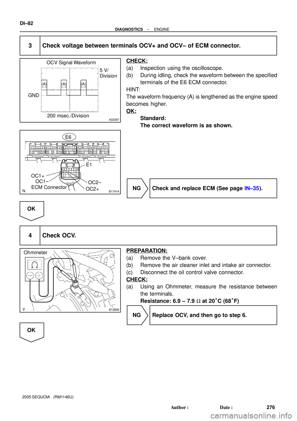
3 Check voltage between terminals OCV+ and OCV± of ECM connector.
CHECK:
(a) Inspection using the oscilloscope.
(b) During idling, check the waveform between the specified
terminals of the E6 ECM connector.
HINT:
The waveform frequency (A) is lengthened as the engine speed
becomes higher.
OK:
Standard:
The correct waveform is as shown.
NG Check and replace ECM (See page IN±35).
OK
4 Check OCV.
PREPARATION:
(a) Remove the V±bank cover.
(b) Remove the air cleaner inlet and intake air connector.
(c) Disconnect the oil control valve connector.
CHECK:
(a) Using an Ohmmeter, measure the resistance between
the terminals.
Resistance: 6.9 ± 7.9 W at 20°C (68°F)
NG Replace OCV, and then go to step 6.
OK
Page 443 of 4323

DTC P0420 Catalyst System Efficiency Below Threshold
(Bank 1)
DTC P0430 Catalyst System Efficiency Below Threshold
(Bank 2)
MO")
± DIAGNOSTICSENGINE
DI±249
443 Author�: Date�:
2005 SEQUOIA (RM1146U)
DTC P0420 Catalyst System Efficiency Below Threshold
(Bank 1)
DTC P0430 Catalyst System Efficiency Below Threshold
(Bank 2)
MONITOR DESCRIPTION
The ECM uses the two sensors, mounted in front of and behind the Three±way Catalytic Converter (TWC),
to monitor its efficiency.
The first sensor, the Air±Fuel Ratio (A/F) sensor (sensor 1), sends pre±catalyst information to the ECM. The
second sensor, the Heated Oxygen (HO2) sensor (sensor 2), sends post±catalyst information to the ECM.
The ECM compares the information transmitted by these two sensors to determine the efficiency of the TWC
performance and its ability to store oxygen.
When the TWC is functioning properly, the variation in the oxygen concentration in the exhaust gas, after
it has passed through the TWC, is small. In this condition, the voltage output of sensor 2 slowly alternates
between the rich and lean signal voltages (shown in the illustration below). As the TWC performance efficien-
cy deteriorates, its oxygen storage capacity decreases, and the variation in the oxygen concentration in the
exhaust gas increases. As a result, the sensor voltage output fluctuates frequently.
While the catalyst monitor is running, the ECM measures the signal lengths of both sensors 1 and 2, and
calculates the ratio of the signal lengths to determine the extent of the TWC deterioration. If the deterioration
level exceeds the preset threshold, the ECM interprets this as the TWC malfunction. The ECM then illumi-
nates the MIL and sets the DTC.
DTC No.DTC Detecting ConditionTrouble Area
P0420
P0430OSC value smaller than standard value under active air±fuel
ratio control (2 trip detection logic)
�Gas leakage on exhaust system
�A/F sensor (Bank 1, 2 sensor 1)
�Heated oxygen sensor (bank 1, 2 sensor 2)
�Three±way catalytic converter
HINT:
�Bank 1 refers to the bank that includes cylinder No.1.
�Bank 2 refers to the bank that does not include cylinder No.1.
�Sensor 1 refers to the sensor mounted in front of the Three±Way Catalytic Converter (TWC) and lo-
cated near the engine assembly.
�Sensor 2 refers to the sensor mounted behind the TWC and located far from the engine assembly.
DID87±01