Page 1131 of 4323
BR3795OKNG
± DIAGNOSTICSABS WITH EBD & BA & TRAC & VSC SYSTEM
DI±929
1123 Author�: Date�:
2005 SEQUOIA (RM1146U)
3 Check for open and short circuit in harness and connector between each speed
sensor and skid control ECU (See page IN±35).
NG Repair or replace harness or connector.
OK
4 Check sensor installation.
CHECK:
Check the speed sensor installation.
OK:
The installation bolt is tightened properly and there is
no clearance between the sensor and the front steer-
ing knuckle or the rear axle carrier.
Torque: 8.0 N´m (82 kgf´cm, 71 in.´lbf)
NG Replace speed sensor
(See page BR±56 or BR±59).
NOTICE:
Check the speed sensor signal after replacement (See
page DI±899).
OK
Page 1132 of 4323

5 Check speed sensor an")
W04200
Normal Signal Waveform
1 V / Division2 m/s / DivisionGND
R07880
DI±930
± DIAGNOSTICSABS WITH EBD & BA & TRAC & VSC SYSTEM
1124 Author�: Date�:
2005 SEQUOIA (RM1146U)
5 Check speed sensor and sensor rotor serrations.
INSPECTION USING OSCILLOSCOPE
PREPARATION:
Connect the oscilloscope to the terminal FR+ ± FR±, FL+ ± FL±,
RR+ ± RR± and RL+ ± RL± of the skid control ECU.
CHECK:
Drive the vehicle at about 12 mph (20 km/h), and check the sig-
nal waveform.
OK:
A waveform as shown in the figure should be output.
HINT:
�As the vehicle speed (wheel revolution speed) increases,
a cycle of the waveform becomes shorter and the fluctua-
tion in the output voltage becomes greater.
�When noise is identified in the waveform on the oscillo-
scope, error signals are generated due to the speed sen-
sor rotor's scratches, looseness or foreign matter depos-
ited on it.
OK Replace skid control ECU
(See page BR±52).
NOTICE:
When replacing the skid control ECU, perform the zero
point calibration (See page DI±897).
NG
6 Check sensor rotor and sensor tip.
Front:
PREPARATION:
Remove the disc (See page SA±22).
CHECK:
Check the sensor rotor serrations.
OK:
No scratches, missing teeth or foreign objects.
PREPARATION:
Remove the front speed sensor (See page BR±56).
CHECK:
Check the sensor tip.
OK:
No scratches or foreign objects on the sensor tip.
HINT:
Remove any foreign matter if identified.
Check the output waveform again after reassembly.
Page 1133 of 4323
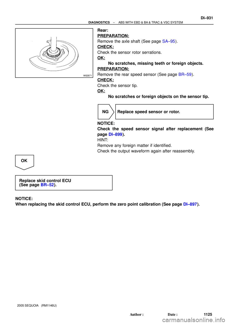
W02871
± DIAGNOSTICSABS WITH EBD & BA & TRAC & VSC SYSTEM
DI±931
1125 Author�: Date�:
2005 SEQUOIA (RM1146U)
Rear:
PREPARATION:
Remove the axle shaft (See page SA±95).
CHECK:
Check the sensor rotor serrations.
OK:
No scratches, missing teeth or foreign objects.
PREPARATION:
Remove the rear speed sensor (See page BR±59).
CHECK:
Check the sensor tip.
OK:
No scratches or foreign objects on the sensor tip.
NG Replace speed sensor or rotor.
NOTICE:
Check the speed sensor signal after replacement (See
page DI±899).
HINT:
Remove any foreign matter if identified.
Check the output waveform again after reassembly.
OK
Replace skid control ECU
(See page BR±52).
NOTICE:
When replacing the skid control ECU, perform the zero point calibration (See page DI±897).
Page 1148 of 4323
DI±946
± DIAGNOSTICSABS WITH EBD & BA & TRAC & VSC SYSTEM
1140 Author�: Date�:
2005 SEQUOIA (RM1146U)
DTCC1231 / 31, C1335 / 35Steering Angle Sensor Circuit
CIRCUIT DESCRIPTION
The steering angle sensor signal is sent to the skid control ECU via the CAN communication system. When
there is a malfunction in the communication system, the DTCs will be detected by the diagnosis function.
DTC No.DTC Detecting ConditionTrouble Area
C1231 / 31Data is not transmitted to the steering angle sensor for a
fixed time invalid steering angle sensor data.
�Translate ECU
�Steering angle sensor
�Steering angle sensor communication circuit
�Skid control ECU
�CAN communication system
C1335 / 35
When the +BS terminal voltage is 9.5 V or more, data trans-
mission from the steering angle sensor is impossible for 1
sec. or more.
�Translate ECU
�Steering angle sensor
�Steering angle sensor to translate ECU circuit
�Skid control ECU
�CAN1 communication system
DI93L±04
Page 1149 of 4323
F19771
F10
Fusible Link BlockInstrument Panel J/BI18
Ignition SWABS & VSC Actuator
(Skid Control ECU)
ALT
B
58W1
1L
1AM1
6
1C
2
4
1F4
1C Sub J/B No.3
8
3C8
3AW±L
12
ECU±IGAM1IG1
B±Y B±R
B±R
B±RB±R
B±R B±RA
J37A
J38
A
J37A
J371
IL113
S1 IG1
1 S7
Steering Angel Sensor
IG
TRIG
SS1±
SS1+
BAT
ESS10
11
3
9
B
BatteryW±L
Y
OL
WL
W Translate ECU
20
T5
19
T5
18
T5
40
T5
1 T5
7
T5
11
T5 TRIG
SS1±
SS1+
GNDIG1
VSC+
VSC±IL2
6
IL26
S1
2
S1
O
P±L P±L
P±L
W±B7
IL2 12
IL1 17
IL19W±B
W±B
W±B41
S1
S1
32
S1CANH
CANL
+BO
GND1
GND2 O
O
O A
A
AA
A
J43
J/CJ18
J/C
IG
IG1 J/C
2
± DIAGNOSTICSABS WITH EBD & BA & TRAC & VSC SYSTEM
DI±947
1141 Author�: Date�:
2005 SEQUOIA (RM1146U)
WIRING DIAGRAM
Page 1150 of 4323

INSPECTION PROCEDURE
HINT:
Start the inspection from step 1 when using the hand±held tester a")
DI±948
± DIAGNOSTICSABS WITH EBD & BA & TRAC & VSC SYSTEM
1142 Author�: Date�:
2005 SEQUOIA (RM1146U)
INSPECTION PROCEDURE
HINT:
Start the inspection from step 1 when using the hand±held tester and start from step 2 when not using the
hand±held tester.
1 Check output value of the steering angle sensor.
PREPARATION:
(a) Connect the hand±held tester to the DLC3.
(b) Turn the ignition switch to the ON position and push the hand±held tester main switch ON.
(c) Check that the steering wheel is centered.
(d) Select DATA LIST mode on the hand±held tester.
CHECK:
Check that the steering wheel turning angle value of the steering angle sensor displayed on the hand±held
tester changes when turning the steering wheel.
ItemMeasurement Item /
Range (Display)Normal ConditionDiagnostic Note
STEERING ANG
Steering sensor/
Min.: ±1152 deg,
Max.: 1150.875 degLeft turn: Increase
Right turn: Decrease±
OK:
Turn the steering wheel to the left: Value increases
Turn the steering wheel to the right: Value decreases
HINT:
If the steering sensor zero point calibration is not performed, its value will be fixed to 1,150 deg.
Check after driving the vehicle straight ahead at a speed of 6.5 mph (10.5 km/h) or more.
OK Go to step 7.
NG
2 Check the installation condition of the steering angle sensor.
CHECK:
Check steering angle sensor installation condition.
OK:
Steering angle sensor installed correctly.
NG Repair or replace steering angle sensor.
NOTICE:
If the steering angle sensor has been replaced, drive the
vehicle straight ahead at a speed of 6.5 mph (10.5 km/h) or
more to calibrate the steering angle sensor.
OK
Page 1151 of 4323
± DIAGNOSTICSABS WITH EBD & BA & TRAC & VSC SYSTEM
DI±949
1143 Author�: Date�:
2005 SEQUOIA (RM1146U)
3 Check for open and short circuit in harness and connector between steering
angle sensor and translate ECU (See page IN±35).
NG Repair or replace harness or connector.
OK
4 Check for open and short circuit in harness and connector between skid control
ECU and translate ECU (CAN1 circuit).
NG Repair or replace harness or connector
(CAN1 circuit).
OK
5 Is DTC still output?
Check DTC on page DI±911.
NO No problem.
YES
Page 1152 of 4323

6 Replace the skid control ECU and check if trouble occurs again.
PREPARATION:
(a) Clear the D")
DI±950
± DIAGNOSTICSABS WITH EBD & BA & TRAC & VSC SYSTEM
1144 Author�: Date�:
2005 SEQUOIA (RM1146U)
6 Replace the skid control ECU and check if trouble occurs again.
PREPARATION:
(a) Clear the DTC.
(b) Turn the ignition switch OFF.
CHECK:
Check if the same DTC still remains in the memory.
RESULT:
DTC is outputA
DTC is not outputB
B END.
A
Replace steering angle sensor.
NOTICE:
�When replacing the skid control ECU, perform the zero point calibration (See page DI±897).
�If the steering angle sensor has been replaced, drive the vehicle straight ahead at a speed of
6.5 mph (10.5 km/h) or more to calibrate the steering angle sensor.
7 Check DTC once more (See page DI±911).
PREPARATION:
(a) Clear the DTC.
(b) Turn the ignition switch OFF.
CHECK:
Check if the same DTC still remains in the memory.
RESULT:
DTC is outputA
DTC is not outputB
B END.
A
Replace skid control ECU with actuator
(See page BR±52).
NOTICE:
When replacing the skid control ECU, perform the zero point calibration (See page DI±897).


ALT
B
58W1
1L
1AM1
6
1C
2
4
1F4
1C Sub J/B No.3
8
3C8
3AW±L
12
ECU±IGAM1IG1
B±Y B±R
B±R
B±")