Page 1164 of 4323
F19145
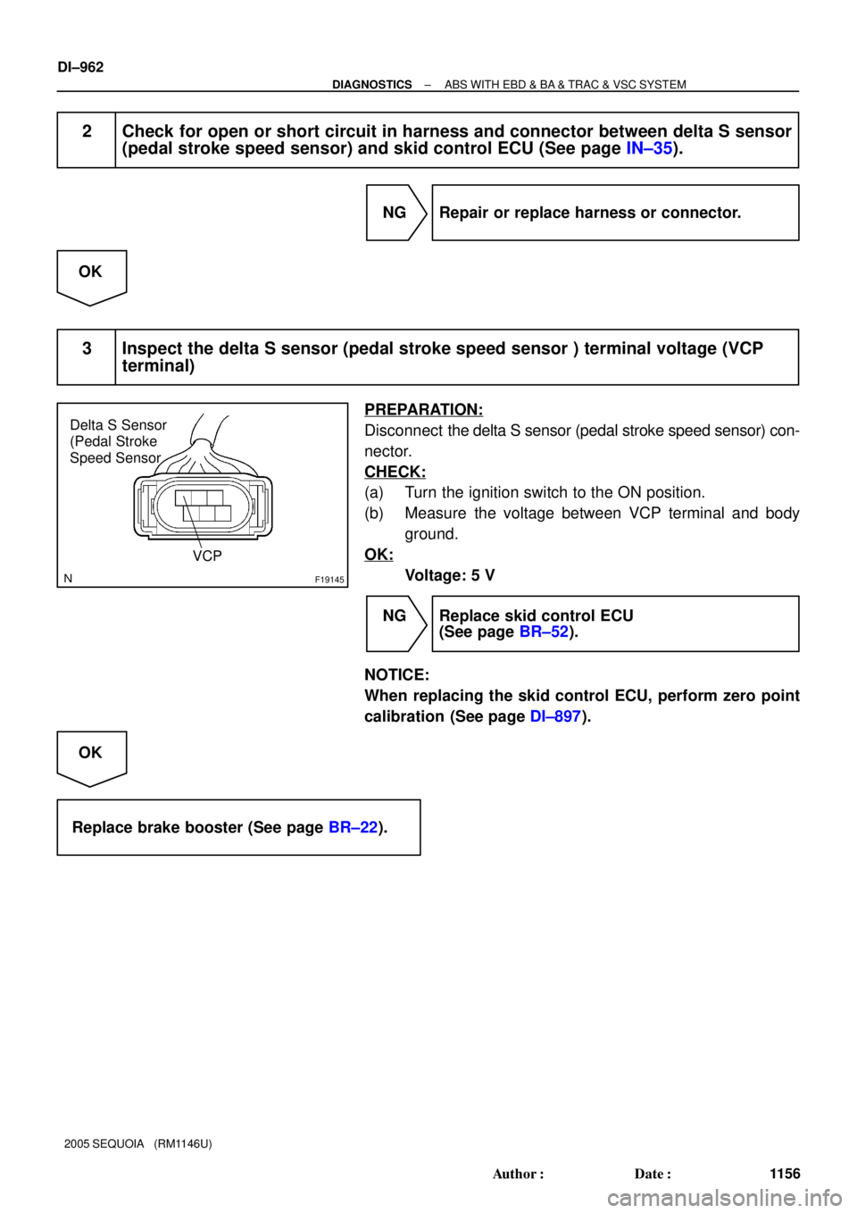
Delta S Sensor
(Pedal Stroke
Speed Sensor
VCP
DI±962
± DIAGNOSTICSABS WITH EBD & BA & TRAC & VSC SYSTEM
1156 Author�: Date�:
2005 SEQUOIA (RM1146U)
2 Check for open or short circuit in harness and connector between delta S sensor
(pedal stroke speed sensor) and skid control ECU (See page IN±35).
NG Repair or replace harness or connector.
OK
3 Inspect the delta S sensor (pedal stroke speed sensor ) terminal voltage (VCP
terminal)
PREPARATION:
Disconnect the delta S sensor (pedal stroke speed sensor) con-
nector.
CHECK:
(a) Turn the ignition switch to the ON position.
(b) Measure the voltage between VCP terminal and body
ground.
OK:
Voltage: 5 V
NG Replace skid control ECU
(See page BR±52).
NOTICE:
When replacing the skid control ECU, perform zero point
calibration (See page DI±897).
OK
Replace brake booster (See page BR±22).
Page 1177 of 4323
± DIAGNOSTICSABS WITH EBD & BA & TRAC & VSC SYSTEM
DI±975
1169 Author�: Date�:
2005 SEQUOIA (RM1146U)
DTC C1337 / 37 Some Tire Are Different in Size From
the Other Tires
CIRCUIT DESCRIPTION
Skid control ECU measure the speed of each wheel by receiving signals from speed sensor. These signals
are used for recognizing all 4 wheels are operating properly. Therefore, all wheel signals must be equal.
DTC No.DTC Detecting ConditionTrouble Area
C1337 / 371 or 2 tires of different size are used for driving.Tire size
INSPECTION PROCEDURE
1 Check tire size.
CHECK:
Check tire size and condition of all 4 wheels.
NG Replace tires so that all 4 tires are the same in
size.
OK
2 Check speed sensor (See page DI±925).
NG Replace speed sensor.
OK
3 Check speed sensor rotor (See page DI±925).
NG Replace speed sensor rotor.
OK
DI93T±03
Page 1178 of 4323
DI±976
± DIAGNOSTICSABS WITH EBD & BA & TRAC & VSC SYSTEM
1170 Author�: Date�:
2005 SEQUOIA (RM1146U)
4 Check harness and connector between speed sensor and skid control ECU
(See page IN±35).
NG Repair or replace harness or connector.
OK
Replace skid control ECU
(See page BR±52).
NOTICE:
When replacing the skid control ECU, perform the zero point calibration (See page DI±897).
Page 1185 of 4323
 M2
Master Cylinder Pressure
Sensor No. 1
VCM
PMC
E1 30
28
29 S1
26
25
27 S1
S1
S1
S1
S1VCM2
PMC2
E2 B
R
W 3
2
1 VCM
PMC
E1
M3
Master Cylinder Pressure")
F16958
ABS & VSC Actuator
(Skid Control ECU ) M2
Master Cylinder Pressure
Sensor No. 1
VCM
PMC
E1 30
28
29 S1
26
25
27 S1
S1
S1
S1
S1VCM2
PMC2
E2 B
R
W 3
2
1 VCM
PMC
E1
M3
Master Cylinder Pressure
Sensor No. 2
3
2
1 VCM2
PMC2
E2B
R
W (Shielded)
(Shielded)J28
J/C A
A A
AW±B Instrument Panel J/B
W±B
J8
J/C
IE1F1K 912BR
BR
± DIAGNOSTICSABS WITH EBD & BA & TRAC & VSC SYSTEM
DI±983
1177 Author�: Date�:
2005 SEQUOIA (RM1146U)
DTC C1360 / 61 Malfunction in Master Cylinder Pres-
sure Sensor
CIRCUIT DESCRIPTION
The master cylinder pressure sensors are connected to the skid control ECU.
Attached to the master cylinder: one reads front master cylinder pressure and the other reads rear master
cylinder pressure.
DTC No.DTC Detecting ConditionTrouble Area
C1360 / 61
When any of the following conditions are detected:
1. Noise to ECU terminal PMC occurs.
2. While ECU terminal STP is OFF, ECU terminal PMC
voltage is out of standard range.
3. When ECU terminal IG1 voltage is proper, ECU terminal
VCM voltage is out of range.
4. When ECU terminal VCM voltage is proper, ECU termi-
nal PMC voltage is out of range.
�Master cylinder pressure sensor
�Master cylinder pressure sensor circuit
WIRING DIAGRAM
DI93V±05
Page 1186 of 4323

INSPECTION PROCEDURE
1 Is pedal lowered or spongy?
YES Bleed air from the system (See page BR�")
DI±984
± DIAGNOSTICSABS WITH EBD & BA & TRAC & VSC SYSTEM
1178 Author�: Date�:
2005 SEQUOIA (RM1146U)
INSPECTION PROCEDURE
1 Is pedal lowered or spongy?
YES Bleed air from the system (See page BR±4).
NO
2 Check output value of the master cylinder pressure sensor No. 1 and No. 2.
PREPARATION:
(a) Connect the hand±held tester to the DLC3.
(b) Turn the ignition switch to the ON position, and push the hand±held tester main switch ON.
(c) Select DATA LIST mode on the hand±held tester.
CHECK:
Check that the brake fluid pressure value of the master cylinder pressure sensor displayed on the hand±held
tester changes when depressing the brake pedal.
ItemMeasurement Item /
Range (Display)Normal ConditionDiagnostic Note
MAS CYL PRS 1
Master cylinder pressure
sensor 1 reading / min.: 0
V, max.: 5 VWhen brake pedal is re-
leased : 0.3 to 0.9 VReading increases when
brake pedal is depressed
MAS CYL PRS 2
Master cylinder pressure
sensor 1 reading / min.: 0
V, max.: 5 VWhen brake pedal is re-
leased : 0.3 to 0.9 VReading increases when
brake pedal is depressed
OK:
Brake fluid pressure value changes.
OK Go to step 4.
NG
3 Check for open and short circuit in harness and connector between master cyl-
inder pressure sensor and skid control ECU (See page IN±35).
NG Repair or replace harness or connector.
OK
Page 1187 of 4323
± DIAGNOSTICSABS WITH EBD & BA & TRAC & VSC SYSTEM
DI±985
1179 Author�: Date�:
2005 SEQUOIA (RM1146U)
4 Replace master cylinder pressure sensor and check DTC once more.
PREPARATION:
(a) Replace the master cylinder pressure sensor (See page BR±16).
(b) Clear the DTC (See page DI±911).
(c) Turn the ignition switch OFF.
CHECK:
Turn the ignition switch to the ON position, and check if the same DTC is stored in the memory.
RESULT:
DTC is outputA
DTC is not outputB
B END
A
Replace skid control ECU
(See page BR±52).
NOTICE:
When replacing the skid control ECU, perform the zero point calibration (See page DI±897).
Page 1188 of 4323
DI±986
± DIAGNOSTICSABS WITH EBD & BA & TRAC & VSC SYSTEM
1180 Author�: Date�:
2005 SEQUOIA (RM1146U)
DTC C1361 / 62 Abnormal Battery Voltage of VSC Sen-
sor
CIRCUIT DESCRIPTION
Supplies power to the VSC sensors (yaw rate and master cylinder pressure sensors) through terminal IG1.
DTC No.DTC Detecting ConditionTrouble Area
C1361/62Voltage from VSC sensor system to ECU is abnormal.
�Battery
�Charging system
�Power source circuit
�Skid control ECU
�Yaw rate (deceleration) sensor
�Master cylinder pressure sensor
DIDME±01
Page 1189 of 4323
M2
Master Cylinder
Pressure Sensor No.1
F19776
ABS & VSC Actuator
(Skid Control ECU)
IG1 13
S1 B±R 1
IL1 B±R B±R B±RA
J38 J/C
A
J37 8
3C 8
3ASub J/B No.3
B±RInstrument Panel J/B
4
1F
1
1L4
1C
6
1C ECU±IG
AM1
WB±Y
W±L
B±Y W±LI18
Ignition SW
12
AM1 IG1Y1
Yaw Rate (Deceleration)
Sensor
(Shield)G 5 3R
R12 11
S1
24
S1VYS
GYAW
E1 VYS
GYAW
BR
(Shield)
B
R
W30
S1
28
S1
29
S1VCM
PMC VCM
PMC
E1
BR
A
A
A
BRJ28
J/C Instrument Panel J/B
9
1F12
1KW±B
W±B
BR
J8
J/C
IE IG(Shield)
1 2 3
B
R
W26
S1
25
S1
27
S1VCM2
PMC2
E2 VCM2
PMC2
E2
1
S1
32
S1GND1
GND2 W±B
W±B W±B
W±B17
IL1
9
IL1 A
A J18
J/C 8
5ALTF10
Fusible
Link
Block12
B
Battery
IMA
J18
J/CM3
Master Cylinder
Pressure Sensor No.2G 11
10 IL1
IL1
IL1
1 2
3
± DIAGNOSTICSABS WITH EBD & BA & TRAC & VSC SYSTEM
DI±987
1181 Author�: Date�:
2005 SEQUOIA (RM1146U)
WIRING DIAGRAM


IG1 13
S1 B±R 1
IL1 B±R B±R B±RA
J38 J/C
A
J37 8
3C 8
3ASub J/B No.3
B±RInstrument Panel J/B
4
1F
1
1L4
1C
6")