Page 1190 of 4323
F19146
Master Cylinder
Pressure Sensor
No. 1Master Cylinder
Pressure Sensor
No. 2
VCM E1VCM2
E2
M3 M2
DI±988
± DIAGNOSTICSABS WITH EBD & BA & TRAC & VSC SYSTEM
1182 Author�: Date�:
2005 SEQUOIA (RM1146U)
INSPECTION PROCEDURE
1 Check battery positive voltage.
OK:
Voltage: 10 to 14 V
NG Check and repair the charging system
(See page CH±1).
OK
2 Check master cylinder pressure sensor No. 1 and No. 2.
PREPARATION:
Disconnect the master cylinder pressure sensor connectors
No. 1 and No. 2.
CHECK:
(1) Turn the ignition switch to the ON position.
(2) Measure the voltage between terminal VCM and
E1, VCM2 and E2 of the harness side connector.
OK:
Voltage: 4.5 to 5.5 V
NG Go to step 4.
OK
Page 1191 of 4323
F19145
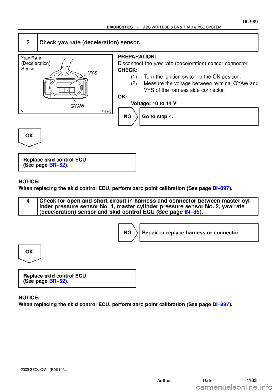
Yaw Rate
(Deceleration)
Sensor
VYS
GYAW
± DIAGNOSTICSABS WITH EBD & BA & TRAC & VSC SYSTEM
DI±989
1183 Author�: Date�:
2005 SEQUOIA (RM1146U)
3 Check yaw rate (deceleration) sensor.
PREPARATION:
Disconnect the yaw rate (deceleration) sensor connector.
CHECK:
(1) Turn the ignition switch to the ON position.
(2) Measure the voltage between terminal GYAW and
VYS of the harness side connector.
OK:
Voltage: 10 to 14 V
NG Go to step 4.
OK
Replace skid control ECU
(See page BR±52).
NOTICE:
When replacing the skid control ECU, perform zero point calibration (See page DI±897).
4 Check for open and short circuit in harness and connector between master cyl-
inder pressure sensor No. 1, master cylinder pressure sensor No. 2, yaw rate
(deceleration) sensor and skid control ECU (See page IN±35).
NG Repair or replace harness or connector.
OK
Replace skid control ECU
(See page BR±52).
NOTICE:
When replacing the skid control ECU, perform zero point calibration (See page DI±897).
Page 1192 of 4323

DTC C1362 / 36 Malfunction in Sensor Offset Value
(VSC Sensor System)
CIRCUIT DESCRIPTION
DTC")
DI±990
± DIAGNOSTICSABS WITH EBD & BA & TRAC & VSC SYSTEM
1184 Author�: Date�:
2005 SEQUOIA (RM1146U)
DTC C1362 / 36 Malfunction in Sensor Offset Value
(VSC Sensor System)
CIRCUIT DESCRIPTION
DTC is output when zero point calibration is not done for the VSC sensors (yaw rate and master cylinder
pressure sensors).
DTC is cleared when zero point calibration is done.
DTC No.DTC Detecting ConditionTrouble Area
C1362 / 36Zero point calibration of the VSC sensor system is not prop-
erly set.Skid control ECU (Perform zero point calibration)
INSPECTION PROCEDURE
1 Perform zero point calibration of the yaw rate (deceleration) sensor and master
cylinder pressure sensor (See page DI±897).
NEXT
2 Check DTC
PREPARATION:
(a) Clear the DTC (See page DI±911).
(b) Turn the ignition switch OFF.
CHECK:
Turn the ignition switch to the ON position, and check if the same DTC still remains in the memory.
RESULT:
DTC is outputA
DTC is not outputB
B END
A
Replace skid control ECU
(See page BR±52).
NOTICE:
When replacing the skid control ECU, perform zero point calibration (See page DI±897).
DI93X±03
Page 1194 of 4323
F19145
Yaw Rate
(Deceleration)
Sensor
STS
DI±992
± DIAGNOSTICSABS WITH EBD & BA & TRAC & VSC SYSTEM
1186 Author�: Date�:
2005 SEQUOIA (RM1146U)
INSPECTION PROCEDURE
1 Check voltage between terminal STS of brake pedal force switch and body
ground.
PREPARATION:
Disconnect the brake pedal force switch connector.
CHECK:
(a) Turn the ignition switch to the ON position.
(b) Measure the voltage between STS of brake pedal force
switch harness side connector and body ground.
OK:
Voltage: About 6 V
NG Go to step 3.
OK
Page 1215 of 4323

DTC Normal Code Malfunction in Translate ECU
CIRCUIT DESCRIPTION
If any trouble occurs in the")
± DIAGNOSTICSABS WITH EBD & BA & TRAC & VSC SYSTEM
DI±1013
1207 Author�: Date�:
2005 SEQUOIA (RM1146U)
DTC Normal Code Malfunction in Translate ECU
CIRCUIT DESCRIPTION
If any trouble occurs in the engine control system, the skid control ECU prohibits ABS & VSC control.
DTC No.DTC Detecting ConditionTrouble Area
Normal Code
Conditions 1., 2. or 3. continue for 5 sec. or more:
1. Engine malfunction signal is sent from ECM.
2. Shift malfunction signal is sent from ECM.
3. The shift position is other than P and N, and P range
input voltage is 8 V or more.
�ECM circuit
�ECM
�Brake fluid level
�Brake fluid level warning switch circuit
�Steering angle sensor
�Translate ECU
�Skid control ECU
�Vehicle CAN
�VSC+, VSC± circuit (CAN1 communication system)
INSPECTION PROCEDURE
1 Is DTC output for ECM?
Check DTC on page DI±43.
YES Repair engine control system according to the
output code (See page DI±58).
NO
2 Check the DTC of the ABS and VSC (See page DI±911).
CHECK:
Check skid control ECU DTC.
RESULT:
Only DTC ºC1203/53º of the VSC system is outputA
Except DTC ºC1203/53º of the VSC system are outputB
B Repair ABS and VSC control system according
to the code output (See page DI±921).
A
DI6OF±12
Page 1259 of 4323
D6
DataLink
Connector
F19789
ABS & VSC Actuator
(Skid Control ECU)
R±L
T5 27
TS2440
S1
12
O
IG TS
CG
4R±LR±L
R±LTS
IL1 Translate ECU
3
O
AA J43
J/C4C 4B
4A6 66 Sub J/B No.4
(*) CAN1 Circuit (*)
± DIAGNOSTICSABS WITH EBD & BA & TRAC & VSC SYSTEM
DI±1057
1251 Author�: Date�:
2005 SEQUOIA (RM1146U)
Ts Terminal Circuit
CIRCUIT DESCRIPTION
In sensor check mode (test mode), a malfunction of the speed sensor that cannot be judged when the vehicle
is stopped is judged while driving.
Transition to sensor check mode (test mode) can be performed by connecting terminals Ts and CG of the
DLC3 and turning the ignition switch from OFF to ON.
WIRING DIAGRAM
DI94A±05
Page 1266 of 4323

SYSTEM DESCRIPTION
1. BRIEF DESCRIPTION
(a) The CAN (Controller Area Network) is a serial data c")
DIDI0±01
DI±1064
± DIAGNOSTICSCAN COMMUNICATION SYSTEM
1258 Author�: Date�:
2005 SEQUOIA (RM1146U)
SYSTEM DESCRIPTION
1. BRIEF DESCRIPTION
(a) The CAN (Controller Area Network) is a serial data communication system for real time application.
It is an in±vehicle multiplex communication system that has a high communication speed (500 kbps)
and the function to detect malfunctions.
(b) By pairing the CANH and CANL bus lines, the CAN performs communication based on differential volt-
age.
(c) Many ECUs (sensors) installed in the vehicle operate by sharing information and communicating with
each other.
(d) The CAN has two resistors of 120 W which are necessary to communicate with the main bus line.
2. DEFINITION OF TERMS
(a) Main bus line
(1) The main bus line is a wire harness between the two terminus circuits on the bus (communication
line). This is the main bus in the CAN communication system.
(b) Sub bus line
(1) The sub bus line is a wire harness that diverges from the main bus line to the ECU.
3. ECUs THAT COMMUNICATE THROUGH CAN COMMUNICATION SYSTEM
(a) Translate ECU
(b) Suspension Control ECU
(c) ECM
4. DIAGNOSTIC CODE FOR CAN COMMUNICATION SYSTEM
DTCs for the CAN communication system are as follows:
U0100/65, U0122/67, U0132/72, 65, 94.
HINT:
If C1201/51, C1202/52 or C1203/53 is output from skid control ECU, perform troubleshooting of each diag-
nosis code (see page DI±921).
5. REMARK FOR TROUBLESHOOTING
(a) Trouble in the CAN bus (communication line) can be checked from the DLC3 (except when there is
a wire break in lines other than the sub bus line of the DLC3).
NOTICE:
Do not insert the tester directly into the DLC3 connector. Be sure to use a service wire.
(b) The CAN communication system cannot detect trouble in the sub bus line of the DLC3 even though
the DLC3 is also connected to the CAN communication system.
6. HOW TO DISTINGUISH THE CAN J/C CONNECTOR
In the CAN communication system, all connectors connected to the CAN J/C are the same shape. The con-
nectors connected to the CAN J/C can be distinguished by the colors of the bus lines.
HINT:
See ºTERMINALS OF ECUº (see page DI±1068) for bus line colors.
Page 1275 of 4323
DIDI5±01
F19740
F19741
F19742
± DIAGNOSTICSCAN COMMUNICATION SYSTEM
DI±1073
1267 Author�: Date�:
2005 SEQUOIA (RM1146U)
DIAGNOSIS SYSTEM
1. BUS CHECK
HINT:
The ECUs that are properly connected to the CAN communica-
tion system can be displayed using the hand±held tester via
CAN VIM.
(a) Select ºBUS CHECKº from the ºOBD/MOBD MENUº
screen.
(b) Press ºENTERº on the hand±held tester via CAN VIM.
(c) The screen displays the ECUs and sensors that are prop-
erly connected to the CAN communication system.
HINT:
There is a communication stop in the system of any properly
connected ECUs or sensors that are not displayed
(see page DI±1067).


R±L
T5 27
TS2440
S1
12
O
IG TS
CG
4R±LR±L
R±LTS
IL1 Translate ECU
3
O
AA J43
J/C4C 4B
4A6 66 Sub J/B No.4
(*) CAN1 Circuit (*)
±")