Page 1153 of 4323

SensorABS & VSC Actuator
(Skid Control ECU)
(Shielded)S1
S1
(Shielded) VYS
YAW 1
GYAWR
B
W
SS2
S1 24 IL1
IL1
IL1
IL143
1")
F16952
VYS
SS1
GYAW S1
23 R
B
W
IM BRIL112
1911
3
12 Y1
Yaw Rate (Deceleration)
SensorABS & VSC Actuator
(Skid Control ECU)
(Shielded)S1
S1
(Shielded) VYS
YAW 1
GYAWR
B
W
SS2
S1 24 IL1
IL1
IL1
IL143
11
10 G
G YAW 2
5(*)
(*)
(*) CAN2 Circuit(*)
(*)
± DIAGNOSTICSABS WITH EBD & BA & TRAC & VSC SYSTEM
DI±951
1145 Author�: Date�:
2005 SEQUOIA (RM1146U)
DTCC1232 / 32, C1244 / 44Deceleration Sensor Circuit
CIRCUIT DESCRIPTION
The skid control ECU receives signals from the yaw rate sensor (deceleration sensor) via the CAN2 commu-
nication system.
The yaw rate sensor has a built±in deceleration sensor.
This sensor detects deceleration on the vehicle. The sensor signal is used in ABS & BA & TRAC & VSC
control.
DTC No.DTC Detecting ConditionTrouble Area
C1232 / 32When the lateral deceleration output becomes 4.8 V or
more or 0.2 V or less per 0.5 second.�Yaw rate (Deceleration) sensor
�Yaw rate (Deceleration) sensor circuit
C1244 / 44
When any of the following conditions are detected:
1. When the supplied voltage to the yaw rate & decelera-
tion sensor becomes 18 V or more or 6.5 V or less.
2. When the longitudinal deceleration output becomes 4.8
V or more or 0.2 V or less per 0.5 second.
�Yaw rate (Deceleration) sensor
�Yaw rate (Deceleration) sensor circuit
WIRING DIAGRAM
DIDM8±01
Page 1154 of 4323

F19199
DI±952
± DIAGNOSTICSABS WITH EBD & BA & TRAC & VSC SYSTEM
1146 Author�: Date�:
2005 SEQUOIA (RM1146U)
INSPECTION PROCEDURE
1 Check the yaw rat")
F19784
Torque: 5 N´m (10 kgf´cm, 3.7ft´lbf)
F19199
DI±952
± DIAGNOSTICSABS WITH EBD & BA & TRAC & VSC SYSTEM
1146 Author�: Date�:
2005 SEQUOIA (RM1146U)
INSPECTION PROCEDURE
1 Check the yaw rate (deceleration) sensor installation.
CHECK:
Check the yaw rate (deceleration) sensor installation.
OK:
The sensor should be tightened to the specified
torque.
The sensor should not be tilted.
NG Install yaw
rate (deceleration) sensor correctly.
OK
2 Check output value of the yaw rate sensor.
PREPARATION:
(a) Remove the 2 bolts and the yaw rate (deceleration) sen-
sor assembly with the connector still connected.
(b) Connect the hand±held tester to the DLC3.
(c) Turn the ignition switch to the ON position and push the
hand±held tester main switch ON.
(d) Select DATA LIST mode on the hand±held tester.
CHECK:
Check that the decelerate value of the deceleration sensor dis-
played on the hand±held tester changes: Place the decelera-
tion sensor vertically to the ground and turn the sensor to the
frontward and rearward.
ItemMeasurement Item /
Range (Display)Normal ConditionDiagnostic Note
DECELERAT SENS
Deceleration sensor 1
reading / min.: ±1.869 G,
max.: 1.869 GApproximately 0 ± 0.13 G
while stationaryReading changes when ve-
hicle is bounced
DECELERAT SENS2
Deceleration sensor 2
reading / min.: ±1.869 G,
max.: 1.869 GApproximately 0 ± 0.13 G
while stationaryReading changes when ve-
hicle is bounced
OK:
Decelerate value changes.
NG Replace yaw rate (deceleration) sensor.
NOTICE:
When replacing the yaw rate (deceleration) sensor, per-
form the zero point calibration (See page DI±897).
OK
Page 1155 of 4323
F19145
Yaw Rate (Decel-
eration) Sensor
VYS
GYAW
± DIAGNOSTICSABS WITH EBD & BA & TRAC & VSC SYSTEM
DI±953
1147 Author�: Date�:
2005 SEQUOIA (RM1146U)
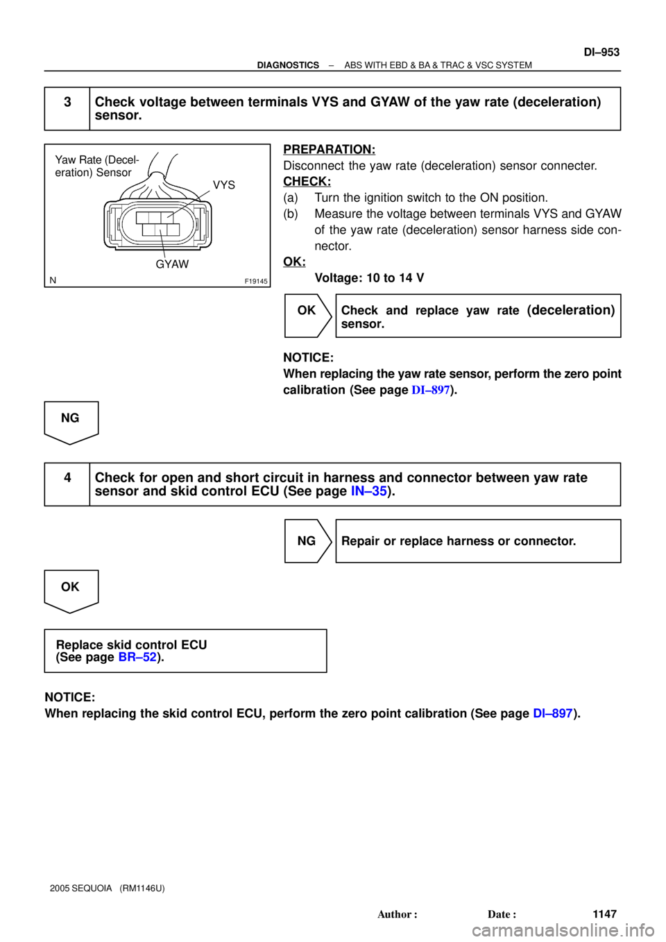
3 Check voltage between terminals VYS and GYAW of the yaw rate (deceleration)
sensor.
PREPARATION:
Disconnect the yaw rate (deceleration) sensor connecter.
CHECK:
(a) Turn the ignition switch to the ON position.
(b) Measure the voltage between terminals VYS and GYAW
of the yaw rate (deceleration) sensor harness side con-
nector.
OK:
Voltage: 10 to 14 V
OK Check and replace yaw rate
(deceleration)
sensor.
NOTICE:
When replacing the yaw rate sensor, perform the zero point
calibration (See page DI±897).
NG
4 Check for open and short circuit in harness and connector between yaw rate
sensor and skid control ECU (See page IN±35).
NG Repair or replace harness or connector.
OK
Replace skid control ECU
(See page BR±52).
NOTICE:
When replacing the skid control ECU, perform the zero point calibration (See page DI±897).
Page 1156 of 4323
S1
S1
(Shielded) VYS
YAW 1
GYAWR
B
W
SS2
S1 24 IL1
IL1
IL1
IL14 3
11
10 G
G YAW 2
5ABS & VSC Actuator
(Skid Control ECU) Y1
Yaw Rate (Dec")
F16952
VYS
SS1
GYAW S1
23 R
B
W
IM BRIL112
1911
3
12
(Shielded)S1
S1
(Shielded) VYS
YAW 1
GYAWR
B
W
SS2
S1 24 IL1
IL1
IL1
IL14 3
11
10 G
G YAW 2
5ABS & VSC Actuator
(Skid Control ECU) Y1
Yaw Rate (Deceleration)
Sensor
(*)
(*)
(*) CAN2 Circuit(*)
(*) DI±954
± DIAGNOSTICSABS WITH EBD & BA & TRAC & VSC SYSTEM
1148 Author�: Date�:
2005 SEQUOIA (RM1146U)
DTC C1234 / 34 Malfunction in Yaw Rate Sensor
CIRCUIT DESCRIPTION
Yaw rate sensor detects the vehicle's sideslip and sends signals to the skid control ECU.
DTC No.DTC Detecting ConditionTrouble Area
C1234 / 34
When any of the following conditions are detected:
1. Power output of 4.65 V or more or 0.25 or less continues
for 0.1 sec. or more.
�Yaw rate (deceleration) sensorC1234 / 34for 0.1 sec. or more.
2. Difference between the actual output value of the yaw
rate sensor and the output value calculated from the
other sensor's continues to be large.�Ya w rate (deceleration) sensor
�Yaw rate (deceleration) sensor circuit
WIRING DIAGRAM
DIDM9±01
Page 1157 of 4323

F16996
± DIAGNOSTICSABS WITH EBD & BA & TRAC & VSC SYSTEM
DI±955
1149 Author�: Date�:
2005 SEQUOIA (RM1146U)
INSPECTION PROCEDURE
1 Check the yaw rat")
F19784
Torque: 5 N´m (10 kgf´cm, 3.7ft´lbf)
F16996
± DIAGNOSTICSABS WITH EBD & BA & TRAC & VSC SYSTEM
DI±955
1149 Author�: Date�:
2005 SEQUOIA (RM1146U)
INSPECTION PROCEDURE
1 Check the yaw rate sensor installation.
CHECK:
Check the yaw rate sensor installation.
OK:
The sensor should be tightened to the specified
torque.
The sensor should not be tilted.
NG Install yaw
rate sensor correctly.
OK
2 Check output value of the yaw rate sensor.
PREPARATION:
(a) Remove the 2 bolts and the yaw rate sensor assembly
with the connector still connected.
(b) Connect the hand±held tester to the DLC3.
(c) Turn the ignition switch to the ON position and push the
hand±held tester main switch ON.
(d) Select the DATA LIST mode on the hand±held tester.
CHECK:
Check that the yaw rate value of the yaw rate sensor displayed
on the hand±held tester changes: Place the yaw rate sensor
vertically to the ground and turn the sensor to the right and left.
ItemMeasurement Item /
Range (Display)Normal ConditionDiagnostic Note
YAW RATE
Yaw rate sensor/
Min.: ±128 deg/s, Max.:
127 deg/sMin.: ±128 deg/s
Max.: 128 deg/s±
OK:
Yaw rate value changes.
NG Replace yaw rate sensor.
NOTICE:
When replacing the yaw rate sensor, perform the zero point
calibration (See page DI±897).
OK
Page 1158 of 4323
F19145
Yaw Rate Sensor
VYS
GYAW
DI±956
± DIAGNOSTICSABS WITH EBD & BA & TRAC & VSC SYSTEM
1150 Author�: Date�:
2005 SEQUOIA (RM1146U)
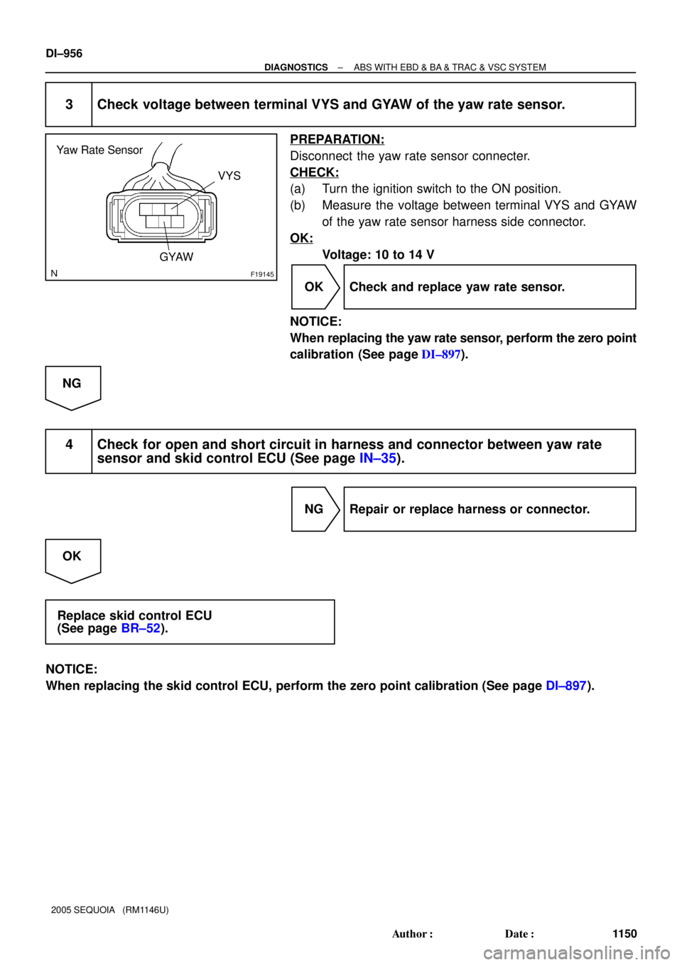
3 Check voltage between terminal VYS and GYAW of the yaw rate sensor.
PREPARATION:
Disconnect the yaw rate sensor connecter.
CHECK:
(a) Turn the ignition switch to the ON position.
(b) Measure the voltage between terminal VYS and GYAW
of the yaw rate sensor harness side connector.
OK:
Voltage: 10 to 14 V
OK Check and replace yaw rate sensor.
NOTICE:
When replacing the yaw rate sensor, perform the zero point
calibration (See page DI±897).
NG
4 Check for open and short circuit in harness and connector between yaw rate
sensor and skid control ECU (See page IN±35).
NG Repair or replace harness or connector.
OK
Replace skid control ECU
(See page BR±52).
NOTICE:
When replacing the skid control ECU, perform the zero point calibration (See page DI±897).
Page 1162 of 4323
F16976
ABS & VSC Actuator
(Skid Control ECU) P20
Pedal Stroke Speed Sensor
(Delta S Sensor)
(Shielded)
Instrument Panel J/BVCP
PIM
E3 S1 3
BR
J28
J/C
A
IEVCP1
S1
S1 8 14
PIM
E3
A
A J8
J/C
W±B W±B
1F
1K12 9 5
3G
Y
L DI±960
± DIAGNOSTICSABS WITH EBD & BA & TRAC & VSC SYSTEM
1154 Author�: Date�:
2005 SEQUOIA (RM1146U)
DTC C1247 / 47 Malfunction in Delta S Sensor
CIRCUIT DESCRIPTION
Detects a problem with booster negative pressure and enters assist control.
DTC No.DTC Detecting ConditionTrouble Area
C1247 / 47
When any of the following conditions are detected:
1. When the output becomes 4.7 V or more or 0.2 V or less
per 100 msec.
2. When the output does not return to 2.5 V even when 500
msec. or more elapse, in spite of no change in brake
operation.
�Brake booster
�Delta S sensor (Pedal stroke speed sensor)
�Delta S sensor (Pedal stroke speed sensor) circuit
�Skid control ECU
WIRING DIAGRAM
DIDMB±01
Page 1163 of 4323
: Brake Pedal
Depressed
(2): Brake Pedal
Released Voltage
Time 4.5 V
1.9 V
0.5 V(2)
(1)
± DIAGNOSTICSABS WITH EBD & BA & TRAC & VSC SYSTEM
DI±961
1155 Author�: Date�:
2005 SEQUOIA (RM11")
F19800
(1): Brake Pedal
Depressed
(2): Brake Pedal
Released Voltage
Time 4.5 V
1.9 V
0.5 V(2)
(1)
± DIAGNOSTICSABS WITH EBD & BA & TRAC & VSC SYSTEM
DI±961
1155 Author�: Date�:
2005 SEQUOIA (RM1146U)
INSPECTION PROCEDURE
HINT:
Start the inspection from step 1 in the case of using the hand±held tester and start from step 2 in the case
of not using the hand±held tester.
1 Check output value of the delta S sensor (pedal stroke speed sensor) using the
hand±held tester.
PREPARATION:
(a) Connect the hand±held tester to the DLC3.
(b) Turn the ignition switch to the ON position.
(c) Run the engine until the engine speed reaches 3,000 rpm, and return it back to idle.
HINT:
Rev up the engine to ensure sufficient vacuum.
(d) Select DATA LIST mode on the hand±held .
ItemMeasurement Item /
Range (Display)Normal ConditionDiagnostic Note
PEDAL STROKEPedal stroke sensor/
min.: 0 V, max.: 5.1 V
Approximately 2.0 V with-
out the brake pedal de-
pressed.
±
HINT:
�The result appears on the tester after some delay because a time lag occurs in measurement with a
hand±held tester.
�If a signal from the delta S sensor is sent between sampling, the result does not appear on the tester.
So be sure to perform the measurement 2 or 3 times.
CHECK:
Check that the brake pedal acceleration value of the delta S sensor displayed on the hand±held tester
changes, alternatively increasing the brake pedal stroke.
OK:
The value changes as shown in the illustration on the
left. (The value will return to approximately 2.0 V after
the brake pedal is released.)
HINT:
The maximum voltage depends on pedal stroke speed but
should not exceed 4.5 V or fall below 0.2 V.
OK Replace skid control ECU
(See page BR±52).
NOTICE:
When replacing the skid control ECU, perform zero point
calibration (See page DI±897).
NG
 P20
Pedal Stroke Speed Sensor
(Delta S Sensor)
(Shielded)
Instrument Panel J/BVCP
PIM
E3 S1 3
BR
J28
J/C
A
IEVCP1
S1
S1 8 14
PIM
E3
A
A J8
J/C
W±B W±B
1F")