Page 3250 of 4323

5. REMOVE COMBINATION SWITCH WITH SPIRAL
CABLE
(a) Disconnect the 4 connectors.")
F17896
A
BMatchmarks
F13260
F06703
± STEERINGTILT STEERING COLUMN
SR±15
3242 Author�: Date�:
2005 SEQUOIA (RM1146U)
5. REMOVE COMBINATION SWITCH WITH SPIRAL
CABLE
(a) Disconnect the 4 connectors.
(b) Disconnect the airbag connector.
(c) Remove the 3 screws and combination switch.
6. REMOVE SPIRAL CABLE (See page BE±26)
NOTICE:
Do not disassemble the cable or apply oil to it.
7. REMOVE COWL SIDE TRIM AND FRONT DOOR
SCUFF PLATE
8. REMOVE LOWER LH FINISH PANEL
(a) Remove the 2 screws and disconnect the hood lock re-
lease lever from the panel.
(b) Remove the 4 panel set bolts and lower LH finish panel.
9. REMOVE NO. 2 HEATER TO REGISTER DUCT
10. REMOVE BRAKE PEDAL RETURN SPRING
11. REMOVE SLIDING YOKE
(a) Put matchmarks on the sliding yoke and No. 2 intermedi-
ate shaft assembly.
(b) Remove the ºAº bolt.
(c) Remove the ºBº bolt.
(d) Slide the sliding yoke and remove it.
12. REMOVE COLUMN HOLE COVER NO. 2
Remove the 3 bolts and column hole cover No. 2.
13. DISCONNECT TRANSMISSION CONTROL CABLE
ASSEMBLY
Disconnect the cable assembly from the column shift lever as-
sembly.
14. REMOVE STEERING COLUMN ASSEMBLY WITH
NO. 2 UNIVERSAL JOINT ASSEMBLY
(a) Disconnect the connectors.
(b) Remove the 4 steering column set nuts.
(c) Pull out the steering column assembly with the No. 2 uni-
versal joint assembly connected.
Page 3252 of 4323
SR0V1±06
F13611
Screw Extractor
F06733
± STEERINGTILT STEERING COLUMN
SR±17
3244 Author�: Date�:
2005 SEQUOIA (RM1146U)
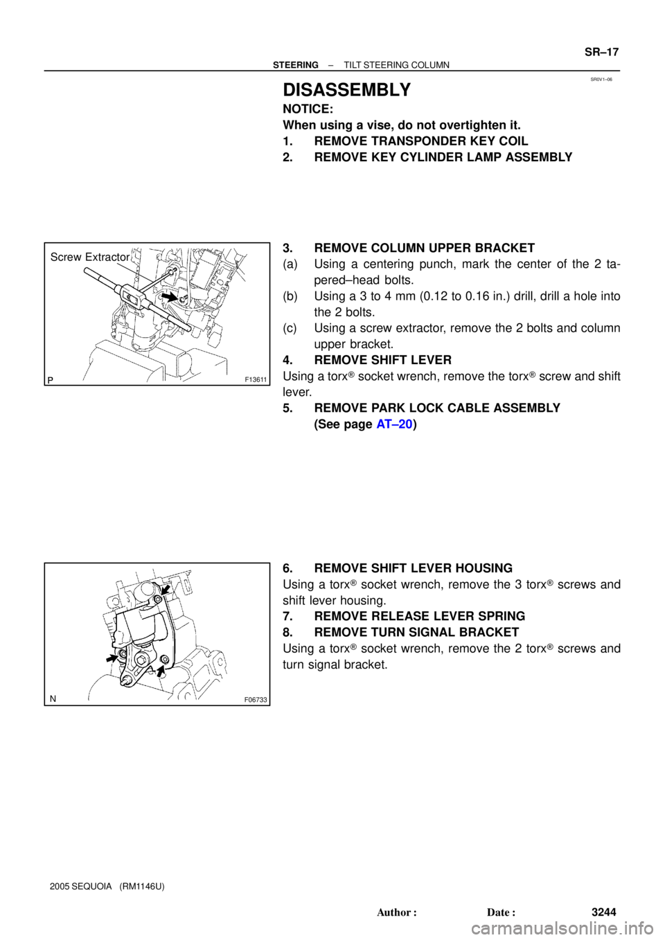
DISASSEMBLY
NOTICE:
When using a vise, do not overtighten it.
1. REMOVE TRANSPONDER KEY COIL
2. REMOVE KEY CYLINDER LAMP ASSEMBLY
3. REMOVE COLUMN UPPER BRACKET
(a) Using a centering punch, mark the center of the 2 ta-
pered±head bolts.
(b) Using a 3 to 4 mm (0.12 to 0.16 in.) drill, drill a hole into
the 2 bolts.
(c) Using a screw extractor, remove the 2 bolts and column
upper bracket.
4. REMOVE SHIFT LEVER
Using a torx® socket wrench, remove the torx® screw and shift
lever.
5. REMOVE PARK LOCK CABLE ASSEMBLY
(See page AT±20)
6. REMOVE SHIFT LEVER HOUSING
Using a torx® socket wrench, remove the 3 torx® screws and
shift lever housing.
7. REMOVE RELEASE LEVER SPRING
8. REMOVE TURN SIGNAL BRACKET
Using a torx® socket wrench, remove the 2 torx® screws and
turn signal bracket.
Page 3254 of 4323

INSPECTION
1. INSPECT STEERING LOCK OPERATION
Check that the steering lock mechanism")
SR0V2±05
F13613
F13618
R11908
± STEERINGTILT STEERING COLUMN
SR±19
3246 Author�: Date�:
2005 SEQUOIA (RM1146U)
INSPECTION
1. INSPECT STEERING LOCK OPERATION
Check that the steering lock mechanism operates properly.
2. IF NECESSARY, REPLACE KEY CYLINDER
(a) Turn the ignition key to the ACC position.
(b) Push down the stop pin with a screwdriver, and pull out
the cylinder.
(c) Install a new cylinder.
HINT:
Make sure that the key is in the ACC position.
3. INSPECT IGNITION SWITCH (See page BE±24)
4. IF NECESSARY, REPLACE IGNITION SWITCH
(a) Remove the 2 screws and ignition switch.
(b) Install a new ignition switch with the 2 screws.
5. INSPECT KEY UNLOCK WARNING SWITCH
(See page BE±24)
6. IF NECESSARY, REPLACE KEY UNLOCK WARNING
SWITCH
(a) Slide out the key unlock warning switch.
(b) Install a new key unlock warning switch.
7. INSPECT TRANSPONDER KEY COIL
(See page BE±143)
8. IF NECESSARY, REPLACE TRANSPONDER KEY
COIL
9. IF NECESSARY, REPLACE TRANSPONDER KEY AM-
PLIFIER
(a) Remove the screw and transponder key amplifier.
(b) Install a new transponder key amplifier with the screw.
10. INSPECT BEARING
(a) Check that the bearing rotates smoothly without abnor-
mal noise.
If it does not rotate smoothly or abnormal noise occurs, replace
the column housing.
(b) Coat the bearing with molybdenum disulfide lithium base
grease.
Page 3257 of 4323

7. INSTALL TURN SIGNAL BRACKET
Using a torx® socket wrench, install the turn signal bracket with
2 n")
F06737
F13612
SR±22
± STEERINGTILT STEERING COLUMN
3249 Author�: Date�:
2005 SEQUOIA (RM1146U)
7. INSTALL TURN SIGNAL BRACKET
Using a torx® socket wrench, install the turn signal bracket with
2 new torx® screws.
Torque: 7.5 N´m (75 kgf´cm, 65 in.´lbf)
HINT:
Make sure that the protrusion on the steering column housing
is fitted into the hole of the turn signal bracket.
8. INSTALL RELEASE LEVER SPRING
9. INSTALL SHIFT LEVER HOUSING
Using a torx® socket wrench, install the shift lever housing with
3 new torx® screws.
Torque: 12 N´m (120 kgf´cm, 9 ft´lbf)
10. INSTALL PARK LOCK CABLE ASSEMBLY (See page
AT±21)
11. INSTALL SHIFT LEVER
Using a torx® socket wrench, install the shift lever with a new
torx® screw.
Torque: 18 N´m (180 kgf´cm, 13 ft´lbf)
12. INSTALL COLUMN UPPER BRACKET
(a) Install the column upper bracket with 2 new tapered±
head bolts.
HINT:
Insert the bracket pin into the column tube hole.
(b) Tighten the tapered±head bolts until the bolt heads break
off.
13. INSTALL KEY CYLINDER LAMP ASSEMBLY
14. INSTALL TRANSPONDER KEY COIL
Page 3262 of 4323
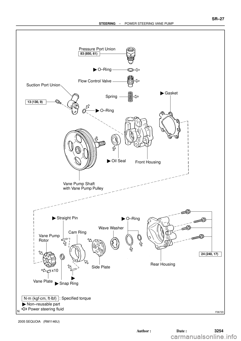
F06720
Pressure Port Union
83 (850, 61)
� O±Ring
Flow Control Valve
Spring
� O±Ring
Suction Port Union
13 (130, 9)
Vane Pump Shaft
with Vane Pump Pulley
� Oil Seal
Front Housing
� Gasket
24 (240, 17)
Rear Housing
� O±Ring
Wave Washer
Side Plate
Cam Ring
� Straight Pin
Vane Pump
Rotor
�
� Snap Ring x10Vane Plate
N´m (kgf´cm, ft´lbf): Specified torque
� Non±reusable part
Power steering fluid
± STEERINGPOWER STEERING VANE PUMP
SR±27
3254 Author�: Date�:
2005 SEQUOIA (RM1146U)
Page 3265 of 4323
SR0RF±05
F06719
Vane Pump Shaft
Front HousingBushing
N00372
HeightThickness
Length
R10282
Feeler Gauge
SR±30
± STEERINGPOWER STEERING VANE PUMP
3257 Author�: Date�:
2005 SEQUOIA (RM1146U)
INSPECTION
1. CHECK OIL CLEARANCE BETWEEN VANE PUMP
SHAFT AND BUSHING
Using a micrometer and caliper gauge, measure the oil clear-
ance.
Standard clearance:
0.03 to 0.05 mm (0.0012 to 0.0020 in.)
Maximum clearance: 0.07 mm (0.0028 in.)
If it is more than the maximum, replace the shaft and front hous-
ing.
2. INSPECT VANE PUMP ROTOR AND VANE PLATES
(a) Using a micrometer, measure the height, thickness and
length of the 10 plates.
Minimum height: 8.6 mm (0.339 in.)
Minimum thickness: 1.397 mm (0.0550 in.)
Minimum length: 14.991 mm (0.5902 in.)
(b) Using a feeler gauge, measure the clearance between
the rotor groove and plate.
Maximum clearance: 0.033 mm (0.0013 in.)
Page 3268 of 4323
SR0RG±09
F01511
Vinyl Tape
F06727
Press
SST
Oil Seal
SST
± STEERINGPOWER STEERING VANE PUMP
SR±33
3260 Author�: Date�:
2005 SEQUOIA (RM1146U)
REPLACEMENT
NOTICE:
When using a vise, do not overtighten it.
IF NECESSARY, REPLACE OIL SEAL
(a) Using a screwdriver with vinyl tape wound around its tip,
remove the oil seal.
NOTICE:
Be careful not to damage the front housing.
(b) Coat a new oil seal lip with power steering fluid.
(c) Using SST, press in the oil seal.
SST 09950±60010 (09951±00330),
09950±70010 (09951±07100)
NOTICE:
Make sure to install the oil seal in the correct direction.
Page 3273 of 4323
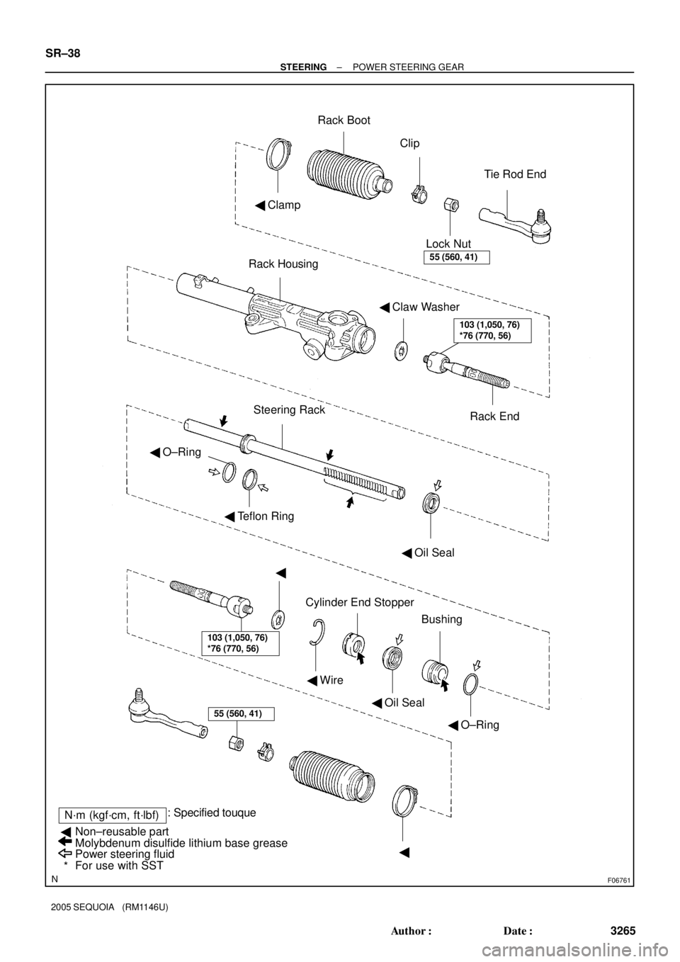
F06761
Rack Housing
� Claw Washer
Rack End Lock NutTie Rod End Rack Boot
� ClampClip
Steering Rack
� Teflon Ring
� Oil Seal
Bushing
� O±Ring � Oil Seal � Wire �
�
N´m (kgf´cm, ft´lbf): Specified touque
Power steering fluid
For use with SST Non±reusable part
Molybdenum disulfide lithium base grease �
*
� O±Ring
55 (560, 41)
103 (1,050, 76)
*76 (770, 56)
55 (560, 41)
103 (1,050, 76)
*76 (770, 56)
Cylinder End Stopper
SR±38
± STEERINGPOWER STEERING GEAR
3265 Author�: Date�:
2005 SEQUOIA (RM1146U)