Page 3274 of 4323
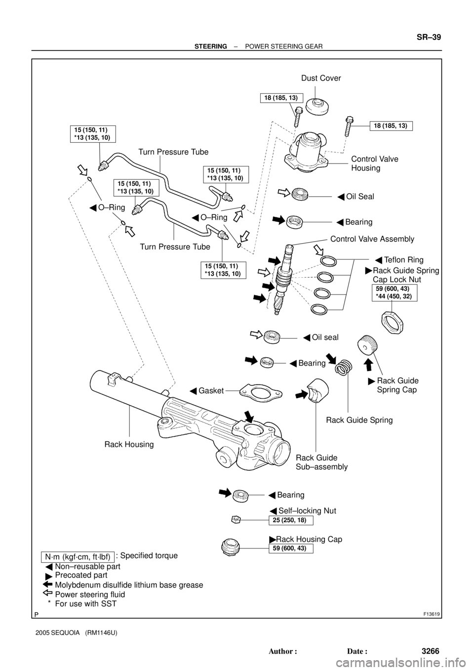
�Rack Housing Cap
59 (600, 43)
F13619
Turn Pressure TubeDust Cover
Turn Pressure Tube� O±RingControl Valve
Housing
� Oil Seal
� Bearing
� Teflon Ring
Rack Guide Spring
Rack Guide
Sub±assembly
� Self±locking Nut � Bearing
N´m (kgf´cm, ft´lbf): Specified torque
Non±reusable part
Precoated part
Molybdenum disulfide lithium base grease
Power steering fluid
For use with SSTRack Housing� Bearing
� GasketControl Valve Assembly
�
�
*� Oil seal
15 (150, 11)
*13 (135, 10)18 (185, 13)
�
59 (600, 43)
*44 (450, 32)
Rack Guide
Spring Cap �
25 (250, 18)
18 (185, 13)
15 (150, 11)
*13 (135, 10)
15 (150, 11)
*13 (135, 10)
15 (150, 11)
*13 (135, 10)
Rack Guide Spring
Cap Lock Nut � O±Ring
± STEERINGPOWER STEERING GEAR
SR±39
3266 Author�: Date�:
2005 SEQUOIA (RM1146U)
Page 3278 of 4323

8. REMOVE RACK HOUSING CAP
Using SST, remove the")
F06753
SST
F06754
SST
F06755
Matchmarks
F06756
Vinyl Tape
Shop Rag
± STEERINGPOWER STEERING GEAR
SR±43
3270 Author�: Date�:
2005 SEQUOIA (RM1146U)
8. REMOVE RACK HOUSING CAP
Using SST, remove the rack housing cap.
SST 09816±30010
9. REMOVE SELF±SOCKING NUT
Using SST, stop the control valve shaft rotation, and remove the
nut.
SST 09616±00011
10. REMOVE DUST COVER
11. REMOVE CONTROL VALVE HOUSING WITH CON-
TROL VALVE ASSEMBLY
(a) Put matchmarks on the control valve housing and rack
housing.
(b) Remove the 2 bolts and control valve housing with control
valve assembly attached.
(c) Remove the gasket from the rack housing.
12. REMOVE CONTROL VALVE ASSEMBLY
(a) To prevent oil seal lip damage, wind vinyl tape around the
serrated part of the valve shaft.
(b) Press out the valve assembly with the oil seal.
NOTICE:
�Place a shop rag between the valve housing and the
blocks.
�Be careful not to drop the valve assembly.
�Be careful not to damage the oil seal lip.
13. REMOVE OIL SEAL
Remove the oil seal from the control valve assembly.
Page 3279 of 4323
R11651
SSTWire Cylinder End
Stopper
F08343
SST
F08340Oil Seal SST
SR±44
± STEERINGPOWER STEERING GEAR
3271 Author�: Date�:
2005 SEQUOIA (RM1146U)
14. REMOVE CYLINDER END STOPPER
(a) Using SST, turn the stopper clockwise until the wire end
can be seen through the service hole.
SST 09631±16010
(b) Using SST, turn the stopper counterclockwise, and re-
move the wire.
SST 09631±16010
15. REMOVE STEERING RACK AND BUSHING
(a) Using SST, press out the steering rack with the bushing.
NOTICE:
Take care not to drop the rack.
SST 09950±70010 (09951±07200)
(b) Remove the bushing from the rack.
(c) Remove the O±ring from the bushing.
16. REMOVE OIL SEAL
Using SST, press out the oil seal.
SST 09950±60010 (09951±00360),
09950±70010 (09951±07360)
Page 3281 of 4323
")
SR0VB±04
F08332
SST
Oil
Seal
Bearing
F08333
SST
SST Bearing
F08335
SST
Bearing
F08334Bearing
SST
F08336
SST
Bearing
SR±46
± STEERINGPOWER STEERING GEAR
3273 Author�: Date�:
2005 SEQUOIA (RM1146U)
REPLACEMENT
NOTICE:
When using a vise, do not overtighten it.
1. IF NECESSARY, REPLACE OIL SEAL AND BEARING
(a) Using SST, press out the oil seal and bearing from the
control valve housing.
SST 09950±60010 (09951±00250),
09950±70010 (09951±07150)
(b) Coat a new oil seal lip with power steering fluid.
(c) Using SST, press in the oil seal.
SST 09950±60010 (09951±00180, 09951±00320,
09952±06010), 09950±70010 (09951±07150)
NOTICE:
Make sure to install the oil seal in the correct direction.
(d) Coat a new bearing with molybdenum disulfide lithium
base grease.
(e) Using SST, press in the bearing.
SST 09950±60010 (09951±00340),
09950±70010 (09951±07150)
2. IF NECESSARY, REPLACE 2 BEARINGS
(a) Using SST, press out the bearing.
SST 09950±60010 (09951±00260),
09950±70010 (09951±07150)
(b) Using SST, press out the bearing from the rack housing.
SST 09950±60010 (09951±00260),
09950±70010 (09951±07150)
Page 3282 of 4323

(c) Coat a")
F08337
Bearing SST
F08338
Bearing SST
F01798Bushing
SSTSST
Oil Seal
F01799
Press
Oil Seal
SST
SST
R10955
± STEERINGPOWER STEERING GEAR
SR±47
3274 Author�: Date�:
2005 SEQUOIA (RM1146U)
(c) Coat a new bearing with molybdenum disulfide lithium
base grease.
(d) Using SST, press in the bearing.
SST 09950±60010 (09951±00310),
09950±70010 (09951±07150)
(e) Coat a new bearing with molybdenum disulfide lithium
base grease.
(f) Using SST, press in the bearing.
SST 09950±60010 (09951±00320),
09950±70010 (09951±07150)
3. IF NECESSARY, REPLACE OIL SEAL
(a) Using SST, remove the oil seal from the bushing.
SST 09527±20011, 09612±24014 (09613±22011)
NOTICE:
Be careful not to damage the bushing.
(b) Coat a new oil seal lip with power steering fluid.
(c) Using SST, press in the oil seal.
SST 09950±60010 (09951±00300, 09951±00460,
09952±06010)
NOTICE:
Make sure to install the oil seal in the correct direction.
4. IF NECESSARY, REPLACE TEFLON RING AND O±
RING
(a) Using a screwdriver, remove the teflon ring and O±ring
from the steering rack.
NOTICE:
Be careful not to damage the groove for the teflon ring.
(b) Coat a new O±ring with power steering fluid and install it
on steering rack.
Page 3284 of 4323

REASSEMBLY
NOTICE:
When using a vise,")
SR02R±09
F08341
SST
Oil Seal
SST
W02101
SST Rack Teeth End
R11574
Vinyl Tape
± STEERINGPOWER STEERING GEAR
SR±49
3276 Author�: Date�:
2005 SEQUOIA (RM1146U)
REASSEMBLY
NOTICE:
When using a vise, do not overtighten it.
1. COAT PARTS INDICATED BY ARROWS WITH POWER
STEERING FLUID OR MOLYBDENUM DISULFIDE
LITHIUM BASE GREASE (See pages SR±37)
2. INSTALL OIL SEAL
(a) Coat a new oil seal lip with power steering fluid.
(b) Using SST, press in the oil seal.
SST 09950±60010 (09951±00330, 09951±00490,
09952±06010), 09950±70010 (09951±07360)
NOTICE:
�Make sure to install the oil seal in the correct direc-
tion.
�Take care that the oil seal does not get reversed as
you install it.
3. INSTALL STEERING RACK
(a) Install SST to the rack.
SST 09631±20051
HINT:
If necessary, scrape the burrs off the rack teeth end and bur-
nish.
(b) Coat the SST with power steering fluid.
(c) Install the steering rack into the rack housing.
NOTICE:
Be careful not to damage the oil seal lip.
(d) Remove the SST.
SST 09631±20051
4. INSTALL BUSHING
(a) Coat a new O±ring with power steering fluid and install it
on the bushing.
(b) To prevent oil seal lip damage, wind vinyl tape on the
steering rack end, and apply power steering fluid.
(c) Install the bushing.
NOTICE:
�Make sure to install the bushing in the correct direc-
tion.
�Be careful not to damage the oil seal lip.
Page 3285 of 4323

5. INSTALL CYLINDER END STOPPER")
R11656
SST
Wire
Cylinder End
Stopper
F06757
SST
F06758
Vinyl Tape
F08339Oil Seal SST
SR±50
± STEERINGPOWER STEERING GEAR
3277 Author�: Date�:
2005 SEQUOIA (RM1146U)
5. INSTALL CYLINDER END STOPPER
(a) Align the installation hole for the wire of the stopper with
the slot of the rack housing.
(b) Install a new wire into the stopper.
(c) Using SST, turn the stopper clockwise 400° to 500°.
SST 09631±16010
6. AIR TIGHTNESS TEST
(a) Install SST to the rack housing.
SST 09631±12071
(b) Apply 53 kPa (400 mmHg, 15.75 in.Hg) of vacuum for
about 30 seconds.
(c) Check that there is no change in the vacuum.
If there is change in the vacuum, check the installation of the oil
seals.
7. INSTALL CONTROL VALVE ASSEMBLY
(a) To prevent oil seal lip damage, wind vinyl tape on the ser-
rated part of the valve shaft.
(b) Coat the teflon rings with power steering fluid.
(c) Install the valve assembly into the valve housing.
NOTICE:
Be careful not to damage the teflon rings and oil seal.
8. INSTALL OIL SEAL
(a) Coat a new oil seal lip with power steering fluid.
(b) Using SST, press in the oil seal.
SST 09612±22011
NOTICE:
Make sure to install the oil seal in the correct direction.
9. INSTALL CONTROL VALVE HOUSING WITH CON-
TROL VALVE ASSEMBLY
(a) Place a new gasket on the rack housing.
(b) Align the matchmarks on the control valve housing with
the one on the rack housing.
(c) Install the 2 bolts.
Torque: 18 N´m (185 kgf´cm, 13 ft´lbf)
Page 3286 of 4323

10. INSTALL SELF±LOCKING NUT
Using SST, stop the control valve shaft")
F06754
SST
F06753
SST
F06759
Punch
F08342
12°
± STEERINGPOWER STEERING GEAR
SR±51
3278 Author�: Date�:
2005 SEQUOIA (RM1146U)
10. INSTALL SELF±LOCKING NUT
Using SST, stop the control valve shaft rotation, install a new
nut.
SST 09616±00011
Torque: 25 N´m (250 kgf´cm, 18 ft´lbf)
11. INSTALL DUST COVER
12. INSTALL RACK HOUSING CAP
(a) Apply sealant to 2 or 3 threads of the rack housing cap.
Sealant:
Part No.08833±00080, THREE BOND 1344,
LOCTITE 242 or equivalent
(b) Using SST, install the rack housing cap.
SST 09816±30010
Torque: 59 N´m (600 kgf´cm, 43 ft´lbf)
(c) Using a punch and hammer, stake the 2 parts of the cap.
13. INSTALL RACK GUIDE SUB±ASSEMBLY, RACK
GUIDE SPRING AND RACK GUIDE SPRING CAP
(a) Install the rack guide sub±assembly and rack guide
spring.
(b) Apply sealant to 2 or 3 threads of the rack guide spring
cap.
Sealant:
Part No.08833±00080, THREE BOND 1344,
LOCTITE 242 or equivalent
(c) Temporarily install the rack guide spring cap.
14. ADJUST TOTAL PRELOAD
(a) To prevent the steering rack teeth from damaging the oil
seal lip, temporarily install the RH and LH rack ends.
(b) Using a hexagon wrench, install the rack guide spring
cap.
Torque: 25 N´m (250 kgf´cm, 18 ft´lbf)
(c) Using a hexagon wrench, return the rack guide spring cap
12 °.