Page 2579 of 4323
I28844
Integration Control
and Panel
2L16
7
R±WRrBLW
RrVM I21 21
BPBH122
G IJ3 A30
A/C Power Transistor
4LG W±G W±B
5 3
B15
Blower Motor
(Rear)12G W±GL
1 w/ Rear A/C:
From
RR Heater RelayI21 IJ3
W±B
A
J57
J/C
± DIAGNOSTICSAIR CONDITIONING SYSTEM
DI±2377
2571 Author�: Date�:
2005 SEQUOIA (RM1146U)
Blower Motor Circuit (Rear A/C)
CIRCUIT DESCRIPTION
This is power source for the blower motor.
WIRING DIAGRAM
DI8AF±06
Page 2583 of 4323
I28845
ECM
E5
E5G±BIntegration Control
and Panel
I22
ACT
AC1
8 25
24
L±W 2
21
5 MG CLT Relay
J3 J/C
15
IG4 C
C Engine Room J/B
2
2C4
2G
3
A3
A/C Magnetic Clutch
and Lock Sensor R±Y
IA1 LG±B5
4
Engine Room R/B No. 2
2 22 G±Y
MGC 5
I19 I22 ACT
AC1
IA5
R±Y1
L±W L±W
R±Y
L
L
± DIAGNOSTICSAIR CONDITIONING SYSTEM
DI±2381
2575 Author�: Date�:
2005 SEQUOIA (RM1146U)
Compressor Circuit
CIRCUIT DESCRIPTION
The integration control and panel outputs the magnetic clutch ON signal from terminal AC1 to the ECM.
When the ECM receives this signal, it sends a signal from terminal ACT and switches the A/C magnetic clutch
relay ON. This turns the A/C magnetic clutch on.
WIRING DIAGRAM
DIAA8±03
Page 2585 of 4323
± DIAGNOSTICSAIR CONDITIONING SYSTEM
DI±2383
2577 Author�: Date�:
2005 SEQUOIA (RM1146U)
3 Perform active test by hand±held tester.
PREPARATION:
(a) Connect the hand±held tester to the DLC3.
(b) Turn the ignition switch ON and push the hand±held tester main SW ON.
CHECK:
Select the item below in the DATA LIST, and read the displays on the hand±held tester.
AIR CONDITIONING:
ItemTest Details / Display (Range)Diagnostic Note
A/C MAG CLUTCHMagnet clutch relay / OFF, ONOperating sound can be heard
HINT:
Check with the engine running.
OK:
The operation sound of the MG CLT relay can be heard.
NG Go to step 5.
OK
4 Check harness and connector between integration control and panel (ACT termi-
nal) and ECM (ACT terminal) (See page IN±35).
NG Repair or replace harness or connector.
OK
Proceed to next circuit inspection shown in problem symptoms table (See page DI±2304).
Page 2586 of 4323
Z18060
15 2
3
12 3 5
I21361
3
DI±2384
± DIAGNOSTICSAIR CONDITIONING SYSTEM
2578 Author�: Date�:
2005 SEQUOIA (RM1146U)
5 Check magnetic clutch relay.
PREPARATION:
Remove the magnetic clutch relay from the engine room J/B.
CHECK:
Measure the resistance according to the value(s) in the table
below.
OK:
Tester connectionConditionSpecified condition
3 ± 5Always10 kW or higher
3 ± 5
Voltage is applied
between terminals
1 and 2Below 1W (Battery
voltage is applied between
terminals 1 and 2)
NG Replace magnetic clutch relay.
OK
6 Check A/C magnetic clutch.
PREPARATION:
Disconnect the magnetic clutch connector.
CHECK:
Connect the positive (+) battery lead to the magnetic clutch con-
nector terminal 3.
OK:
Magnetic clutch is energized.
NG Replace A/C magnetic clutch.
OK
7 Check harness and connector between integration control and panel (MGC ter-
minal) and body ground (See page IN±35).
NG Repair or replace harness or connector.
OK
Replace integration control and panel.
Page 2666 of 4323

EM120±07
B07536
Disconnect
± ENGINE MECHANICALENGINE UNIT (2WD)
EM±79
2658 Author�: Date�:
2005 SEQUOIA (RM1146U)
REMOVAL
1. REMOVE ENGINE HOOD
2. REMOVE ENGINE UNDER COVER
3. DISCONNECT BATTERY CABLES
(a) Disconnect the clamp on battery negative (±) cable from
the No.2 relay box.
(b) Disconnect the battery positive (+) terminal cable.
(c) Disconnect battery negative (±) cable from the left fender
apron.
4. DRAIN ENGINE COOLANT
5. REMOVE RADIATOR ASSEMBLY (See page CO±17)
6. REMOVE THROTTLE BODY COVER
7. REMOVE AIR CLEANER AND INTAKE AIR CONNEC-
TOR ASSEMBLY
(a) Disconnect the MAF meter connector.
(b) Loosen the 3 bolts, and remove the air cleaner case.
(c) Remove the suction hose from the intake air connector.
(d) Disconnect the PS air hose, air inlet hose for EVAP, PCV
hose and MAF meter wire from the air intake connector.
(e) Disconnect the intake air connector from the throttle body.
8. REMOVE DRIVE BELT, FAN, FLUID COUPLING AND
FAN PULLEY
(a) Loosen the 4 nuts holding the fluid coupling to the fan
bracket.
(b) Remove the drive belt. (See page CH±7)
(c) Remove the 4 nuts, the fan, fluid coupling assembly and
fan pulley.
9. DISCONNECT ENGINE WIRE FROM CABIN
(a) Remove the glove compartment door.
(b) Remove the lower No.2 panel.
(c) Remove the 3 screws, and disconnect the ECM from the
body bracket.
(d) Disconnect the 3 wire harness connectors from the ECM.
(e) Disconnect the 2 wire harness connectors (cassette con-
nector).
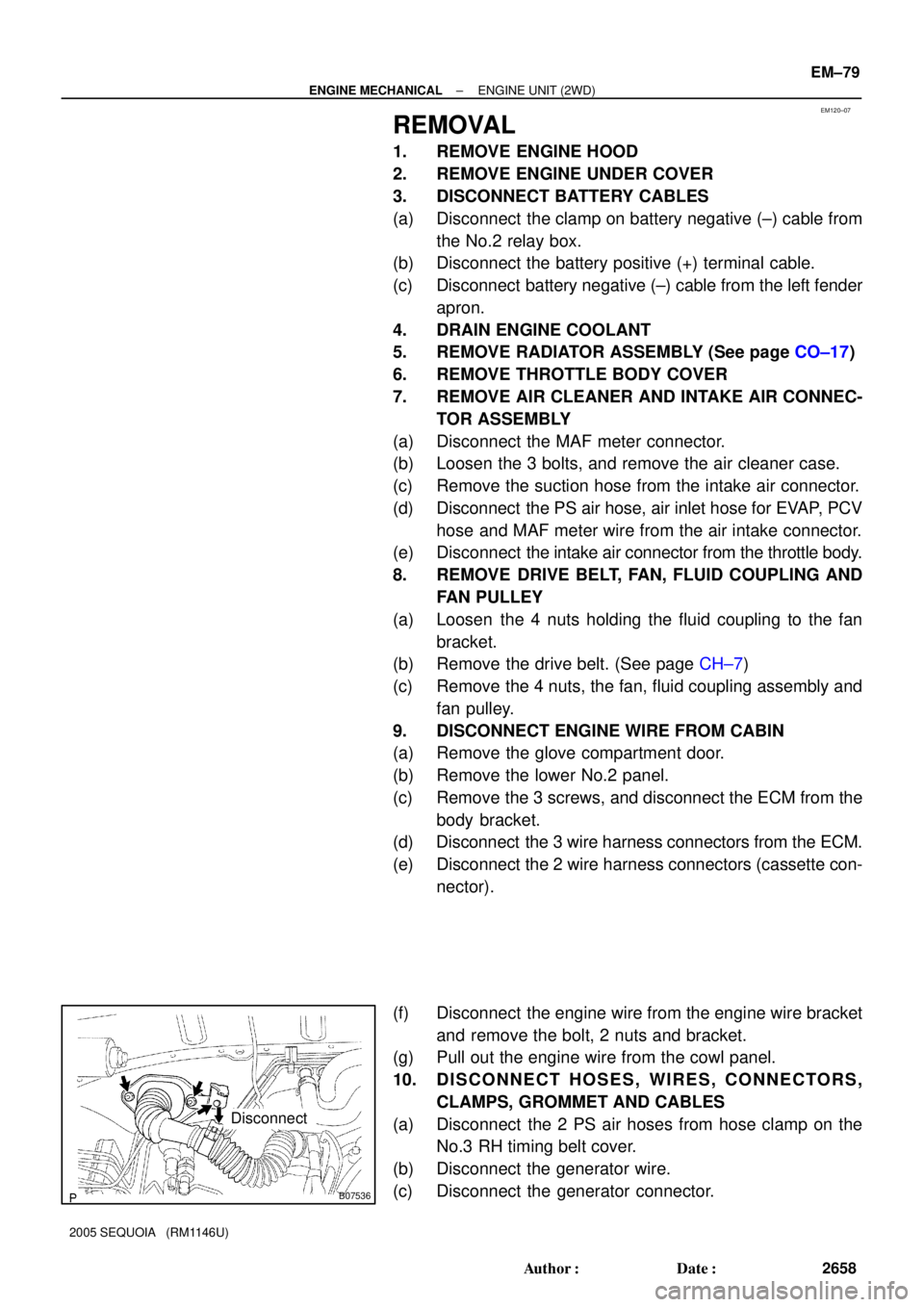
(f) Disconnect the engine wire from the engine wire bracket
and remove the bolt, 2 nuts and bracket.
(g) Pull out the engine wire from the cowl panel.
10. DISCONNECT HOSES, WIRES, CONNECTORS,
CLAMPS, GROMMET AND CABLES
(a) Disconnect the 2 PS air hoses from hose clamp on the
No.3 RH timing belt cover.
(b) Disconnect the generator wire.
(c) Disconnect the generator connector.
Page 2674 of 4323

A09152
Connect
± ENGINE MECHANICALENGINE UNIT (2WD)
EM±87
2666 Author�: Date�:
2005 SEQUOIA (RM1146U)
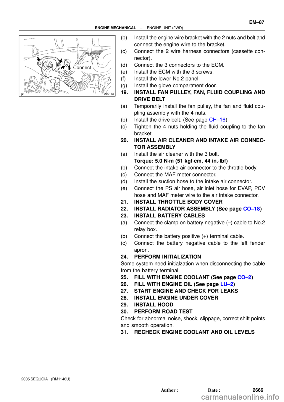
(b) Install the engine wire bracket with the 2 nuts and bolt and
connect the engine wire to the bracket.
(c) Connect the 2 wire harness connectors (cassette con-
nector).
(d) Connect the 3 connectors to the ECM.
(e) Install the ECM with the 3 screws.
(f) Install the lower No.2 panel.
(g) Install the glove compartment door.
19. INSTALL FAN PULLEY, FAN, FLUID COUPLING AND
DRIVE BELT
(a) Temporarily install the fan pulley, the fan and fluid cou-
pling assembly with the 4 nuts.
(b) Install the drive belt. (See page CH±16)
(c) Tighten the 4 nuts holding the fluid coupling to the fan
bracket.
20. INSTALL AIR CLEANER AND INTAKE AIR CONNEC-
TOR ASSEMBLY
(a) Install the air cleaner with the 3 bolt.
Torque: 5.0 N´m (51 kgf´cm, 44 in.´lbf)
(b) Connect the intake air connector to the throttle body.
(c) Connect the MAF meter connector.
(d) Install the suction hose to the intake air connector.
(e) Connect the PS air hose, air inlet hose for EVAP, PCV
hose and MAF meter wire to the air intake connector.
21. INSTALL THROTTLE BODY COVER
22. INSTALL RADIATOR ASSEMBLY (See page CO±18)
23. INSTALL BATTERY CABLES
(a) Connect the clamp on battery negative (±) cable to No.2
relay box.
(b) Connect the battery positive (+) terminal cable.
(c) Connect the battery negative cable to the left fender
apron.
24. PERFORM INITIALIZATION
Some system need initialzation when disconnecting the cable
from the battery terminal.
25. FILL WITH ENGINE COOLANT (See page CO±2)
26. FILL WITH ENGINE OIL (See page LU±2)
27. START ENGINE AND CHECK FOR LEAKS
28. INSTALL ENGINE UNDER COVER
29. INSTALL HOOD
30. PERFORM ROAD TEST
Check for abnormal noise, shock, slippage, correct shift points
and smooth operation.
31. RECHECK ENGINE COOLANT AND OIL LEVELS
Page 2679 of 4323

EM11X±07
EM±92
± ENGINE MECHANICALENGINE UNIT (4WD)
2671 Author�: Date�:
2005 SEQUOIA (RM1146U)
REMOVAL
1. REMOVE FRONT EXHAUST PIPES
(See page EM±126)
2. REMOVE FRONT AND REAR PROPELLER SHAFTS
(See page PR±7)
3. REMOVE FRONT STABILIZER BAR
(See page SA±91)
4. REMOVE TRANSMISSION (See page AT±25)
5. REMOVE ENGINE HOOD
6. REMOVE ENGINE UNDER COVER
7. DISCONNECT BATTERY CABLES
(a) Disconnect the clamp on battery negative (±) cable from
the No.2 relay box.
(b) Disconnect the battery positive (+) terminal cable.
(c) Disconnect the battery negative (±) cable from the left
fender apron.
8. DRAIN ENGINE COOLANT
9. REMOVE RADIATOR ASSEMBLY (See page CO±17)
10. REMOVE THROTTLE BODY COVER
11. REMOVE AIR CLEANER AND INTAKE AIR CONNEC-
TOR ASSEMBLY
(a) Disconnect the MAF meter connector.
(b) Loosen the 3 bolts, and remove the air cleaner case.
(c) Remove the suction hose from the intake air connector.
(d) Disconnect the PS air hose, air inlet hose for EVAP, PCV
hose and MAF meter wire from the air intake connector.
(e) Disconnect the intake air connector from the throttle body.
12. REMOVE DRIVE BELT, FAN, FLUID COUPLING AND
FAN PULLEY
(a) Loosen the 4 nuts holding the fluid coupling to the fan
bracket.
(b) Remove the drive belt. (See page CH±16)
(c) Remove the 4 nuts, the fan, fluid coupling assembly and
fan pulley.
13. DISCONNECT ENGINE WIRE FROM CABIN
(a) Remove the glove compartment door.
(b) Remove the lower No.2 panel.
(c) Remove the 3 screws, and disconnect the ECM from the
body bracket.
(d) Disconnect the 3 wire harness connectors from the ECM.
(e) Disconnect the 2 wire harness connectors (cassette con-
nector).
Page 2684 of 4323

A09152
Connect
± ENGINE MECHANICALENGINE UNIT (4WD)
EM±97
2676 Author�: Date�:
2005 SEQUOIA (RM1146U)
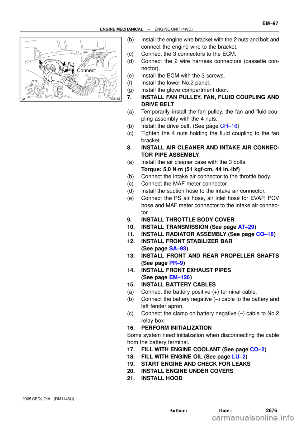
(b) Install the engine wire bracket with the 2 nuts and bolt and
connect the engine wire to the bracket.
(c) Connect the 3 connectors to the ECM.
(d) Connect the 2 wire harness connectors (cassette con-
nector).
(e) Install the ECM with the 3 screws.
(f) Install the lower No.2 panel.
(g) Install the glove compartment door.
7. INSTALL FAN PULLEY, FAN, FLUID COUPLING AND
DRIVE BELT
(a) Temporarily install the fan pulley, the fan and fluid cou-
pling assembly with the 4 nuts.
(b) Install the drive belt. (See page CH±16)
(c) Tighten the 4 nuts holding the fluid coupling to the fan
bracket.
8. INSTALL AIR CLEANER AND INTAKE AIR CONNEC-
TOR PIPE ASSEMBLY
(a) Install the air cleaner case with the 3 bolts.
Torque: 5.0 N´m (51 kgf´cm, 44 in.´lbf)
(b) Connect the intake air connector to the throttle body.
(c) Connect the MAF meter connector.
(d) Install the suction hose to the intake air connector.
(e) Connect the PS air hose, air inlet hose for EVAP, PCV
hose and MAF meter connector to the intake air connec-
tor.
9. INSTALL THROTTLE BODY COVER
10. INSTALL TRANSMISSION (See page AT±29)
11. INSTALL RADIATOR ASSEMBLY (See page CO±18)
12. INSTALL FRONT STABILIZER BAR
(See page SA±93)
13. INSTALL FRONT AND REAR PROPELLER SHAFTS
(See page PR±9)
14. INSTALL FRONT EXHAUST PIPES
(See page EM±126)
15. INSTALL BATTERY CABLES
(a) Connect the battery positive (+) terminal cable.
(b) Connect the battery negative (±) cable to the battery and
left fender apron.
(c) Connect the clamp on battery negative (±) cable to No.2
relay box.
16. PERFORM INITIALIZATION
Some system need initialzation when disconnecting the cable
from the battery terminal.
17. FILL WITH ENGINE COOLANT (See page CO±2)
18. FILL WITH ENGINE OIL (See page LU±2)
19. START ENGINE AND CHECK FOR LEAKS
20. INSTALL ENGINE UNDER COVERS
21. INSTALL HOOD