Page 3432 of 4323

INSPECTION
1. INSPECT MAIN SWITCH CONTINUITY")
BE2MU±01
I27713
I27712
I05027
3
15
2 52
3
1
I24374
Wire Harness Side: BE±20
± BODY ELECTRICALPOWER OUTLET
3424 Author�: Date�:
2005 SEQUOIA (RM1146U)
INSPECTION
1. INSPECT MAIN SWITCH CONTINUITY
Switch positionTester connectionSpecified condition
ON3 ± 5Continuity
OFF3 ± 5No continuity
Constant4 ± 5Continuity
Illumination circuit1 ± 2Continuity
If continuity is not as specified, replace the switch.
2. INSPECT MAIN INDICATOR LIGHT OPERATION
(a) Connect the positive (+) lead from the battery to terminal
1 and the negative (±) lead to terminal 2.
(b) Push the main switch and check that the indicator light
comes on.
If operation is not as specified, replace the switch.
3. INSPECT INVERTER RELAY CONTINUITY
ConditionTester connectionSpecified condition
Constant1 ± 2Continuity
Constant3 ± 5No continuity
Apply B+ between
terminals 1 and 23 ± 5Continuity
If continuity is not as specified, replace the relay.
4. INSPECT VOLTAGE INVERTER CIRCUIT
Disconnect the connector from the voltage inverter and inspect
the connector on the wire harness side as shown in the table
below.
Switch positionTester connectionSpecified condition
ON1 ± 4Battery positive voltage
OFF1 ± 4No voltage
If the circuit is not as specified, inspect the circuits connected
to other parts.
Page 3437 of 4323
BE0HV±12
I28402
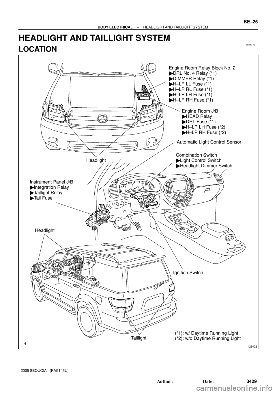
Engine Room Relay Block No. 2
� DRL No. 4 Relay (*1)
� DIMMER Relay (*1)
� H±LP LL Fuse (*1)
� H±LP RL Fuse (*1)
� H±LP LH Fuse (*1)
� H±LP RH Fuse (*1)
Headlight
Combination Switch
� Light Control Switch
� Headlight Dimmer Switch
Ignition Switch
Taillight
Instrument Panel J/B
� Integration Relay
� Taillight Relay
� Tail Fuse
Headlight
Engine Room J/B
� HEAD Relay
� DRL Fuse (*1)
� H±LP LH Fuse (*2)
� H±LP RH Fuse (*2)
Automatic Light Control Sensor
(*1): w/ Daytime Running Light
(*2): w/o Daytime Running Light
± BODY ELECTRICALHEADLIGHT AND TAILLIGHT SYSTEM
BE±25
3429 Author�: Date�:
2005 SEQUOIA (RM1146U)
HEADLIGHT AND TAILLIGHT SYSTEM
LOCATION
Page 3439 of 4323

I12794
13 16 15 14 9 8
17 HIAUTO
LO
OFF
FlashTAIL
3
21 54 6
7
10 12 11
BE2MT±01
I18635
1
2 34
5
I0502712
3 5
1
2 3
5
I18635
1
2 34
5
± BODY ELECTRICALHEADLIGHT AND TAILLIGHT SYSTEM
BE±27
3431 Author�: Date�:
2005 SEQUOIA (RM1146U)
INSPECTION
1. INSPECT LIGHT CONTROL SWITCH CONTINUITY
Switch positionTester connectionSpecified condition
OFF±No continuity
TAIL14 ± 16Continuity
HEAD13 ± 14 ± 16Continuity
AUTO12 ± 16Continuity
If continuity is not as specified, replace the switch.
2. INSPECT HEADLIGHT DIMMER SWITCH CONTINU-
ITY
Switch positionTester connectionSpecified condition
Flash7 ± 8 ± 16Continuity
Low beam16 ± 17Continuity
High beam7 ± 16Continuity
If continuity is not as specified, replace the switch.
3. INSPECT HEAD RELAY CONTINUITY
ConditionTester connectionSpecified condition
Constant1 ± 2Continuity
Constant3 ± 5No continuity
Apply B+ between
terminals 1 and 2.3 ± 5Continuity
If continuity is not as specified, replace the relay.
4. INSPECT TAILLIGHT RELAY CONTINUITY
ConditionTester connectionSpecified condition
Constant1 ± 2Continuity
Constant3 ± 5No continuity
Apply B+ between
terminals 1 and 2.3 ± 5Continuity
If continuity is not as specified, replace the relay.
5. INSPECT DRL NO. 4 RELAY CONTINUITY (w/ Daytime
Running Light)
ConditionTester connectionSpecified condition
Constant1 ± 2Continuity
Constant3 ± 5No continuity
Apply B+ between
terminals 1 and 2.3 ± 5Continuity
If continuity is not as specified, replace the relay.
Page 3440 of 4323

6. INSPECT DIMMER RELAY CONTINUITY (w/ Daytime
Running Light)
Condi")
I18559
1
2 34
5
I19450
I19451
BE±28
± BODY ELECTRICALHEADLIGHT AND TAILLIGHT SYSTEM
3432 Author�: Date�:
2005 SEQUOIA (RM1146U)
6. INSPECT DIMMER RELAY CONTINUITY (w/ Daytime
Running Light)
ConditionTester connectionSpecified condition
Constant1 ± 2, 3 ± 4Continuity
Apply B+ between
terminals 1 and 2.3 ± 5Continuity
If continuity is not as specified, replace the relay.
7. AUTO ON:
INSPECT AUTOMATIC LIGHT CONTROL
(a) Turn the ignition switch ON.
(b) Turn the light control switch to AUTO.
(c) Gradually cover the top of the sensor.
(d) Check that the accessory lights and the headlights should
turn ON.
8. AUTO OFF:
INSPECT AUTOMATIC LIGHT CONTROL
(a) Gradually expose the sensor.
(b) Check that the headlights and the accessory lights should
turn OFF.
9. INSPECT LIGHTS±OFF CONDITION
(a) Turn the ignition switch ON.
(b) Lights auto ON:
Gradually cover the top of the sensor.
(c) Check that the lights go off under the following conditions.
(1) Light control switch is OFF.
(2) The area surrounding the sensor gets bright.
(3) After the ignition switch is turned OFF and after 30
sec. from when open doors are all closed.
10. INSPECT LIGHTS±ON CONDITION
(a) Open the driver's door while the ignition switch is OFF.
(b) Turn the light control switch to AUTO leaving the door
open and cover the top of the sensor. Make sure that the
lights go on when the ignition switch is turned ON.
11. ADJUST AUTOMATIC LIGHT CONTROL SENSOR
(See page DI±1684)
Page 3445 of 4323
BE050±15
I28403
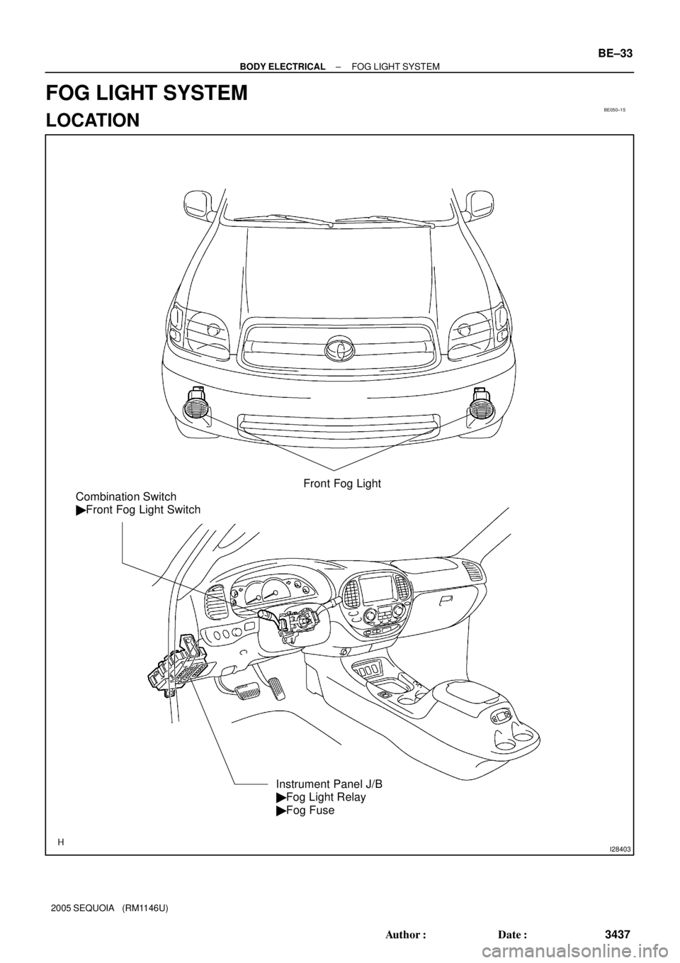
Front Fog Light
Combination Switch
� Front Fog Light Switch
Instrument Panel J/B
� Fog Light Relay
� Fog Fuse
± BODY ELECTRICALFOG LIGHT SYSTEM
BE±33
3437 Author�: Date�:
2005 SEQUOIA (RM1146U)
FOG LIGHT SYSTEM
LOCATION
Page 3446 of 4323
BE0HZ±08
I12795
OFFON
54
1 2 3
15 166
7 8
9 10
11 17
14 13 12
I05027
1 2
3 55
2 13
BE±34
± BODY ELECTRICALFOG LIGHT SYSTEM
3438 Author�: Date�:
2005 SEQUOIA (RM1146U)
INSPECTION
1. INSPECT FOG LIGHT SWITCH CONTINUITY
Switch positionTester connectionSpecified condition
OFF±No continuity
ON10 ± 11Continuity
If continuity is not as specified, replace the switch.
2. INSPECT FOG LIGHT RELAY CONTINUITY
ConditionTester connectionSpecified condition
Constant1 ± 2Continuity
Constant3 ± 5No continuity
Apply B+ between
terminals 1 and 2.3 ± 5Continuity
If continuity is not as specified, replace the relay.
Page 3447 of 4323
BE033±09
I28404
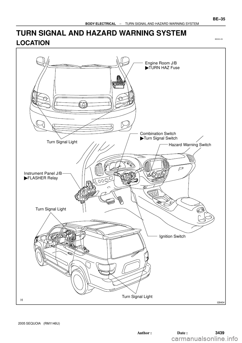
Turn Signal LightHazard Warning Switch Combination Switch
� Turn Signal Switch
Ignition Switch Instrument Panel J/B
� FLASHER Relay
Turn Signal Light
Turn Signal Light
Engine Room J/B
� TURN HAZ Fuse
± BODY ELECTRICALTURN SIGNAL AND HAZARD WARNING SYSTEM
BE±35
3439 Author�: Date�:
2005 SEQUOIA (RM1146U)
TURN SIGNAL AND HAZARD WARNING SYSTEM
LOCATION
Page 3449 of 4323
I24334
Turn Signal Flasher Relay
Connector Front View:
I28728
10
19
± BODY ELECTRICALTURN SIGNAL AND HAZARD WARNING SYSTEM
BE±37
3441 Author�: Date�:
2005 SEQUOIA (RM1146U)
3. Connector connected:
INSPECT TURN SIGNAL FLASHER RELAY OPERA-
TION
Connect the wire harness side connector to the turn signal
flasher and inspect the connector from the back side, as shown.
Tester connectionConditionSpecified condition
2 ± GroundTurn signal switch RIGHTBattery positive voltage e 0 V
3 ± GroundTurn signal switch LEFTBattery positive voltage e 0 V
If operation is not as specified, replace the relay.
4. INSPECT HAZARD WARNING SWITCH CONTINUITY
(a) Remove the center cluster finish panel.
(b) Disconnect the connector from the integrated center clus-
ter.
(c) Check that continuity exists between terminals 19 and 10
with the switch ON.
(d) Check that no continuity exists between terminals 19 and
10 with the switch OFF.
If continuity is not as specified, replace the switch.