Page 3422 of 4323
 Some of the system does not operate.
(Taillight does not come on.)
1. TAIL Fuse
2. TAILLIGHT Relay
3. Light Contr")
BE±10
± BODY ELECTRICALTROUBLESHOOTING
3414 Author�: Date�:
2005 SEQUOIA (RM1146U) Some of the system does not operate.
(Taillight does not come on.)
1. TAIL Fuse
2. TAILLIGHT Relay
3. Light Control Switch
4. Wire Harness
5. Body ECUBE±14
BE±27
BE±27
±
±
Some of the system do not operate.
(Theft deterrent horn or vehicle horn does not sound.)
1. HORN Fuse
2. SECURITY HORN Fuse
3. HORN Relay Circuit
4. Theft Deterrent Horn Circuit
5. Horn
6. Body ECUBE±14
BE±14
BE±145
BE±92
BE±145
±
While the warning is given, the system cannot be canceled by
unlocking the door with a key or transmitter.
1. Door Key Lock and Unlock Switch Circuit (Driver Door
ECU)
Door Key Lock and Unlock Switch Circuit (Passenger
Door ECU)
Door Key Lock and Unlock Switch Circuit (Back Door
ECU)
2. Body ECUDI±1794
DI±1832
DI±1882
±
*1: w/ Glass breakage sensor
WIRELESS DOOR LOCK CONTROL SYSTEM
This system uses the multiplex communication system, so check diagnosis system of the multiplex commu-
nication system before you proceed with troubleshooting.
HINT:
�Troubleshooting of the wireless door lock control system is based on the premise that the door lock
control system operates normally. Accordingly, before troubleshooting the wireless door lock control
system, first make certain that the door lock control system operates normally.
�If the trouble still reappears even though there are no abnormalities in any of the other circuits, check
and replace the Wireless Door Lock Control Receiver as the last step.
SymptomSuspect AreaSee page
All functions of wireless door lock control system do not operate.
1. Transmitter
2. Wireless Door Lock Control Receiver Circuit
3. Body ECUBE±98
DI±1737
±
Wireless door lock operates, but the buzzer does not sound.
(The buzzer does not sound when the customize function prohib-
its.)1. Wireless Door Lock Buzzer Circuit
2. Body ECUDI±1741
±
POWER SEAT CONTROL SYSTEM (w/o Driving Position Memory)
SymptomSuspect AreaSee page
Both Driver and Passenger Power seats do not operate.1. PWR SEAT Fuse
2. Wire HarnessBE±14
±
Driver's seat does not operate.1. Power Seat Switch (D)
2. Wire HarnessBE±109
±
Passenger's seat does not operate.1. Power Seat Switch (P)
2. Wire HarnessBE±109
±
ºSlide operationº does not operate.
1. Power Seat Switch (D, P)
2. Slide Motor (D, P)
3. Wire HarnessBE±109
BE±109
±
ºFront Vertical Operationº does not operate.
1. Power Seat Switch (D)
2. Front Vertical Motor (D)
3. Wire HarnessBE±109
BE±109
±
ºLifter Operationº does not operate.
1. Power Seat Switch (D)
2. Lifter Motor (D)
3. Wire HarnessBE±109
BE±109
±
Page 3424 of 4323

NAVIGATION SYSTEM
SymptomSuspect AreaSee page
Navigation system abnormal operation.See DIAGNOSIS SYSTEMDI±2172
R")
BE±12
± BODY ELECTRICALTROUBLESHOOTING
3416 Author�: Date�:
2005 SEQUOIA (RM1146U)
NAVIGATION SYSTEM
SymptomSuspect AreaSee page
Navigation system abnormal operation.See DIAGNOSIS SYSTEMDI±2172
REAR SEAT ENTERTAINMENT SYSTEM
SymptomSuspect AreaSee page
Rear seat entertainment system abnormal operation.See DIAGNOSIS SYSTEMDI±2083
REAR SEAT AUDIO SYSTEM
SymptomSuspect AreaSee page
Rear seat audio system abnormal operation.See DIAGNOSIS SYSTEMDI±2048
CLOCK SYSTEM
SymptomSuspect AreaSee page
Clock does not operate.TROUBLESHOOTING NO.1BE±127
Clock loses or gains time.TROUBLESHOOTING NO.2BE±127
GARAGE DOOR OPENER SYSTEM
SymptomSuspect AreaSee page
The equipment of which code has been registered does not oper-
ate.1. Garage Door Opener Switch
2. Wire Harness
3. *BE±134
±
±
LED does not come on. (Even though either switch is pressed.)1. Garage Door Opener Switch
2. Wire HarnessBE±134
±
LED does not come on. (Only one switch is pressed.)Garage Door Opener SwitchBE±134
* As the GARAGE DOOR OPENER on the vehicle side seems to be normal, check the OPENER on the
equipment side, of which code has been registered.
ENGINE IMMOBILISER SYSTEM
SymptomSuspect AreaSee page
Engine immobilizer system does not operate.See DIAGNOSIS SYSTEMBE±143
HORN SYSTEM
This system uses the multiplex communication system, so check diagnosis system of the multiplex commu-
nication system before you proceed with troubleshooting.
SymptomSuspect AreaSee page
Horn system does not operate.
1. HORN Fuse
2. HORN Relay Circuit
3. Horn Switch Circuit
4. Horn
5. Body ECUBE±14
BE±145
BE±145
BE±145
±
Horn blow all the time.
1. HORN Relay Circuit
2. Horn Switch Circuit
3. Body ECUBE±145
BE±145
±
One horn operates but the other horn does not operate.1. Horn
2. Wire HarnessBE±145
±
Page 3425 of 4323
± BODY ELECTRICALTROUBLESHOOTING
BE±13
3417 Author�: Date�:
2005 SEQUOIA (RM1146U)
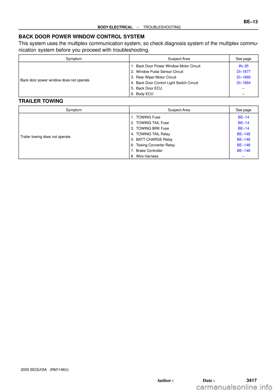
BACK DOOR POWER WINDOW CONTROL SYSTEM
This system uses the multiplex communication system, so check diagnosis system of the multiplex commu-
nication system before you proceed with troubleshooting.
SymptomSuspect AreaSee page
Back door power window does not operate.
1. Back Door Power Window Motor Circuit
2. Window Pulse Sensor Circuit
3. Rear Wiper Motor Circuit
4. Back Door Control Light Switch Circuit
5. Back Door ECU
6. Body ECUIN±35
DI±1877
DI±1880
DI±1864
±
±
TRAILER TOWING
SymptomSuspect AreaSee page
Trailer towing does not operate.
1. TOWING Fuse
2. TOWING TAIL Fuse
3. TOWING BRK Fuse
4. TOWING TAIL Relay
5. BATT CHARGE Relay
6. Towing Converter Relay
7. Brake Controller
8. Wire HarnessBE±14
BE±14
BE±14
BE±148
BE±148
BE±148
BE±148
±
Page 3427 of 4323
I28398
Fuses:Relays:
1. *1 H±LP LL
2. *1 H±LP RL
3. STA
4. *1 H±LP LH
5. *1 H±LP RH
A
G
FED
BC
6
1034
5
A. AIR SUS Relay
B. CDS FAN Relay
C. MG CLT Relay
D. A/F Relay
E. *1 DRL No. 4 Relay
F. DIMMER Relay
G. ST Relay
*1 w/ Daytime Running Light Engine Room R/B No. 2
7
8
911
12
6. AIR SUS No. 2
7. RSE
8. A/F
9. SECURITY
10. DEF I/UP
11. ±
12. ±12
10 A
10 A
7.5 A
10 A
10 A
10 A
7.5 A
20 A
15 A
7.5 A
± BODY ELECTRICALPOWER SOURCE
BE±15
3419 Author�: Date�:
2005 SEQUOIA (RM1146U)
Page 3428 of 4323
I18638
A. Taillight Relay Instrument Panel J/B:
Relays:
B. Back±Up Light Relay
C. ACC Relay
D. Power Main Relay
E. Fog Light Relay
F. MIRROR HEATER Relay
G. FLASHER Relay
H. SEAT HEATER Relay
Fuses:
1. TAIL Fuse
2. PWR No. 4 Fuse
3. PANEL Fuse
4. ECU±IG Fuse
123
4567
89
1011
12
1314
A
BC
DE
GH
F
15
1617 18 19
20
21 22 23
2425
265. CIG Fuse
6. PWR No. 1 Fuse
7. HTR Fuse
8. WSH Fuse
9. RAD No. 2 Fuse
10. WIP Fuse
11. FOG Fuse
12. AC INV Fuse 15 A
13. 4WD Fuse14. IGN1 Fuse
15. GAUGE Fuse
16. IGN 2 Fuse
17. STOP Fuse
18. SUN ROOF Fuse
19. PWR OUTLET Fuse
20. PWR No. 3 Fuse
21. OBD Fuse
22. PWR No. 2 Fuse
23. SEAT HTR Fuse
24. PWR SEAT Fuse
25. AM1 Fuse
26. PWR No. 5 Fuse 15 A 10 A
20 A
7.5 A
10 A
15 A
25 A
10 A
25 A
7.5 A
25 A
15 A
20 A15 A
20 A
15 A
25 A
15 A
20 A
7.5 A
25 A
15 A
30 A
40 A
30 A BE±16
± BODY ELECTRICALPOWER SOURCE
3420 Author�: Date�:
2005 SEQUOIA (RM1146U)
Page 3429 of 4323

I28399
Fusible Link Block:
Relays: Fuses:
5. RR HEATER Fuse 30 A
A. C/OPN Relay
B. HEAD Relay
C. EFI Relay
D. FUEL PUMP Relay
E. DEFOG Relay
F. HORN Relay
Engine Room J/B6. R/B Fuse 30 A
7. A/PUMP Fuse 50 A
8. ABS Fuse 60 A
9. ALT Fuse 140 A
10. CDS FAN Fuse 25 A
11. Spare Fuse 15 A
12. Spare Fuse 20 A
13. Spare Fuse 30 A
14. Main Fuse 40 A
15. DOOR No. 2 Fuse 30 A
16. *2 H±LP RH Fuse 15 A
17. EFI No. 1 Fuse 20 A
18. ETCS Fuse 10 A19. *1.DRL Fuse 15 A
*2.H±LP LH Fuse 15 A
20. ALT±S Fuse 7.5 A
21. TOWING Fuse 30 A
22. ST Fuse 30 A
23. RAD No. 3 Fuse 30 A
24. TURN±HAZ Fuse 20 A
25. AM2 Fuse 25 A
26. EFI No. 2 Fuse 10 A
27. SHORT±PIN
28. HORN Fuse 10 A
29. MIR HTR Fuse 15 A
30. ECU±B Fuse 7.5 A
31. DOME Fuse 10 A
32. RAD No. 1 Fuse 20 A
*1 w/ Daytime Running Light
*2 w/o Daytime Running Light 15
16 17 18
19 20 21
262728
2930
A
B
C
D
EF 1
234
5
6789
10
22 2324 25
31
32
11
12
13141. TOWING R/B Fuse 50 A
2. AIR SUS Fuse 50 A
3. HEATER Fuse 50 A
4. DEFOG Fuse 40 A
± BODY ELECTRICALPOWER SOURCE
BE±17
3421 Author�: Date�:
2005 SEQUOIA (RM1146U)
Page 3430 of 4323
I28550
Engine Room R/B No. 3:
Relays: Fuses:
1. TOWING BRK Fuse 30 A
A. BATT CHARGE Relay
B. TOWING TAIL Relay 2. BATT CHARGE Fuse 30 A
3. TOWING TAIL Fuse 30 A
Driver Side R/B:
Relays:
A. INVERTER Relay
B. SEAT HEATER RelayEngine Room R/B No. 4:
Relays:
A. RR HEATER Relay
B. HEATER Relay BE±18
± BODY ELECTRICALPOWER SOURCE
3422 Author�: Date�:
2005 SEQUOIA (RM1146U)
Page 3431 of 4323
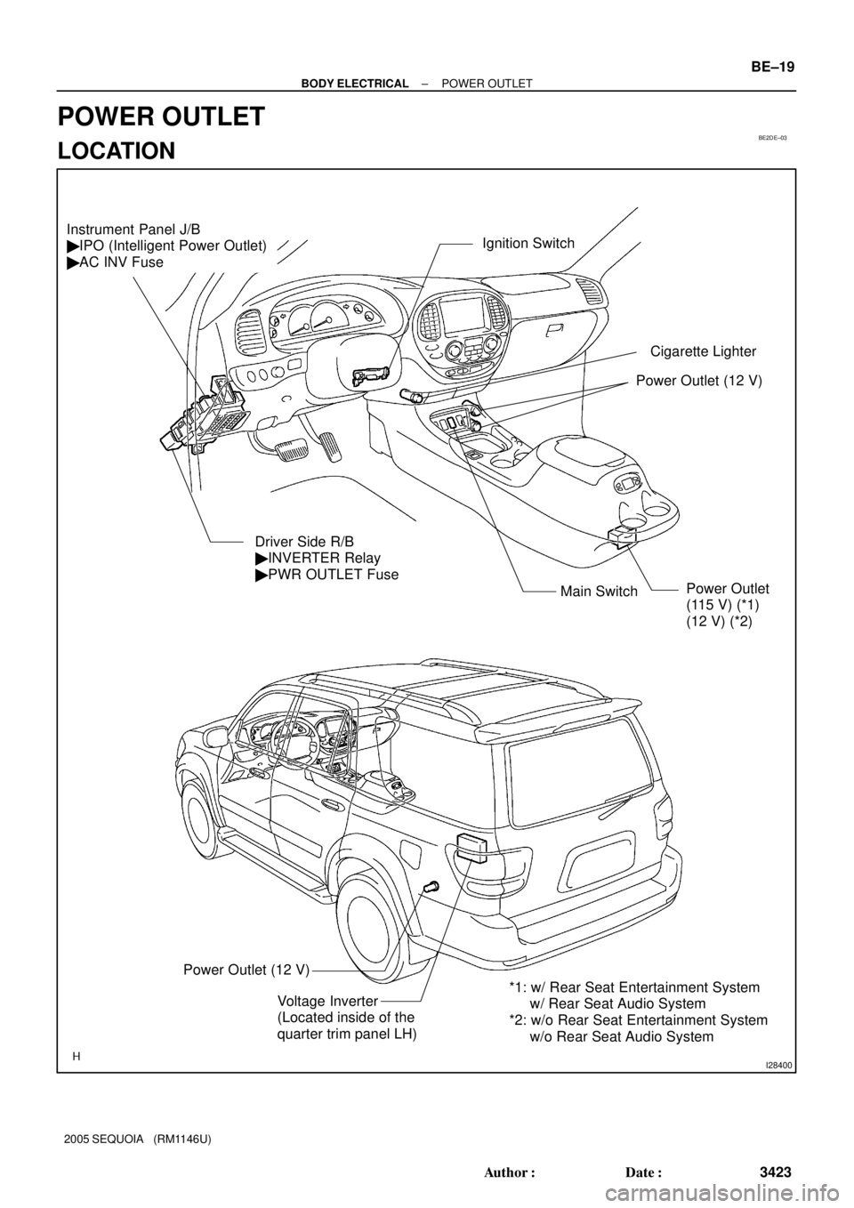
BE2DE±03
I28400
Power Outlet (12 V)
Power Outlet
(115 V) (*1)
(12 V) (*2) Ignition Switch
Main Switch
Instrument Panel J/B
� IPO (Intelligent Power Outlet)
� AC INV Fuse
Driver Side R/B
� INVERTER Relay
� PWR OUTLET Fuse
Power Outlet (12 V)
*1: w/ Rear Seat Entertainment System
w/ Rear Seat Audio System
*2: w/o Rear Seat Entertainment System
w/o Rear Seat Audio System
Voltage Inverter
(Located inside of the
quarter trim panel LH)
Cigarette Lighter
± BODY ELECTRICALPOWER OUTLET
BE±19
3423 Author�: Date�:
2005 SEQUOIA (RM1146U)
POWER OUTLET
LOCATION