Page 2462 of 4323
I28766
R6
Light Control
Rheostat AssyRadio and Navigation Assy
J/C
Steering Pad Switch Assy
Spiral Cable
Sub±assy From
TAILLIGHT
RelayILL±
SWG J/C
ILL+ W±G
GJ39 J40
J39 J40
J39 J40W±G
G
G
G A B
A
AAB
ILL±
T12
2
6 1
10C9±1
BR±W
C9±10 6
4
Steering SWR30
R27 R30 DI±2260
± DIAGNOSTICSNAVIGATION SYSTEM
2454 Author�: Date�:
2005 SEQUOIA (RM1146U)
Illumination circuit
CIRCUIT DESCRIPTION
Power is supplied to the radio and navigation panel illumination when the light control switch is in the TAIL
or HEAD position. The body ECU determines the external brightness based on the brightness level detected
by the automatic light control sensor, and then operates the TAILLIGHT relay. Power can also be supplied
by operating the relay.
The intensity of the radio receiver panel illumination can be adjusted by the rheostat switch.
WIRING DIAGRAM
DIDDF±01
Page 2501 of 4323
DIDKN±01
I28851
R/B No. 2
� Heater Main Relay
(Marking: HTR)
Compressor
Condenser
Receiver Pressure Switch
Integration Panel Assembly
� A/C ECU
� A/C Switch
� Air Inlet Selector
Heater Unit
� Heater Radiator
� Air Mix Servomotor
� Air Outlet Servomotor
Cooling Unit
� Blower Motor Linear
Controller
� Evaporator
� Expansion Valve
� ThermistorBlower Unit
� Blower Motor
� Air Inlet Servomotor
Water Valve
Rear Heater
Control Assembly
Condenser Fan
Ambient
Temperature
Sensor
Solar Sensor
Room
Temperature
Sensor
Rear Room Temperature
± DIAGNOSTICSAIR CONDITIONING SYSTEM
DI±2299
2493 Author�: Date�:
2005 SEQUOIA (RM1146U)
LOCATION
Page 2505 of 4323

DIDKO±01
I15897R/F SW
I15897DEF. SW
STEP
1
2
3
4
5
6
7
8
9
10DISPLAY
CODE
Fr
BLOWER
LEVELFr
OUTLETINLET
COMPRESSORFr A/M
DAMPERRr
BLOWER
LEVELRr
OUTLETRr A/M
DAMPER
1
2
3
4
5
6
7
8
9 0
1 0
16
31FACE
B/L
FOOT
F/D
DEFFRS
R/F (50%)
RECOFF
ON±14%
50.0%
113.5%1 0
10
31FACE1
FACE2
B/L1
B/L2
FOOT0.0%
40.0%
60.0%
86.5%
± DIAGNOSTICSAIR CONDITIONING SYSTEM
DI±2303
2497 Author�: Date�:
2005 SEQUOIA (RM1146U)
ACTUATOR CHECK
1. ACTUATOR CHECK
(a) After entering the sensor check mode, press the R/F
switch (See page DI±2312).
(b) Since each damper, motor and relay automatically oper-
ates at 1 second intervals beginning in order from 20 in
the temperature display, check the temperature and air
flow visually and by hand.
If a slower display is desired, press the DEF. (Fr.) switch
and change it to step operation. Each time the DEF. (Fr.)
switch is pressed, the display changes by 1 step.
HINT:
�Codes are displayed in order from the smallest to the larg-
est numbers.
�To cancel the check mode, press the OFF switch.
Page 2506 of 4323

DI3F3±10
DI±2304
± DIAGNOSTICSAIR CONDITIONING SYSTEM
2498 Author�: Date�:
2005 SEQUOIA (RM1146U)
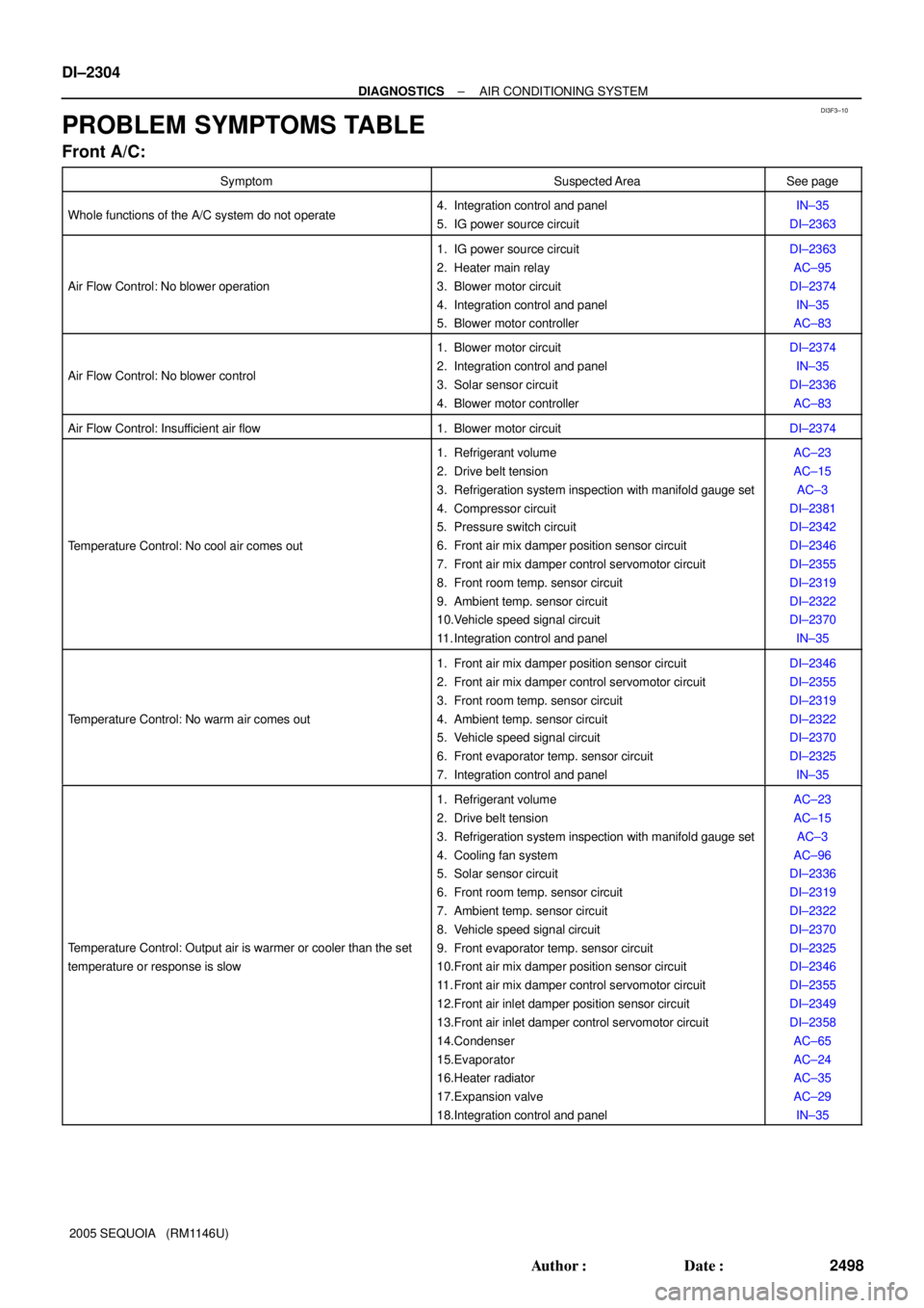
PROBLEM SYMPTOMS TABLE
Front A/C:
SymptomSuspected AreaSee page
Whole functions of the A/C system do not operate4. Integration control and panel
5. IG power source circuitIN±35
DI±2363
Air Flow Control: No blower operation
1. IG power source circuit
2. Heater main relay
3. Blower motor circuit
4. Integration control and panel
5. Blower motor controllerDI±2363
AC±95
DI±2374
IN±35
AC±83
Air Flow Control: No blower control
1. Blower motor circuit
2. Integration control and panel
3. Solar sensor circuit
4. Blower motor controllerDI±2374
IN±35
DI±2336
AC±83
Air Flow Control: Insufficient air flow1. Blower motor circuitDI±2374
Temperature Control: No cool air comes out
1. Refrigerant volume
2. Drive belt tension
3. Refrigeration system inspection with manifold gauge set
4. Compressor circuit
5. Pressure switch circuit
6. Front air mix damper position sensor circuit
7. Front air mix damper control servomotor circuit
8. Front room temp. sensor circuit
9. Ambient temp. sensor circuit
10.Vehicle speed signal circuit
11. Integration control and panelAC±23
AC±15
AC±3
DI±2381
DI±2342
DI±2346
DI±2355
DI±2319
DI±2322
DI±2370
IN±35
Temperature Control: No warm air comes out
1. Front air mix damper position sensor circuit
2. Front air mix damper control servomotor circuit
3. Front room temp. sensor circuit
4. Ambient temp. sensor circuit
5. Vehicle speed signal circuit
6. Front evaporator temp. sensor circuit
7. Integration control and panelDI±2346
DI±2355
DI±2319
DI±2322
DI±2370
DI±2325
IN±35
Temperature Control: Output air is warmer or cooler than the set
temperature or response is slow
1. Refrigerant volume
2. Drive belt tension
3. Refrigeration system inspection with manifold gauge set
4. Cooling fan system
5. Solar sensor circuit
6. Front room temp. sensor circuit
7. Ambient temp. sensor circuit
8. Vehicle speed signal circuit
9. Front evaporator temp. sensor circuit
10.Front air mix damper position sensor circuit
11. Front air mix damper control servomotor circuit
12.Front air inlet damper position sensor circuit
13.Front air inlet damper control servomotor circuit
14.Condenser
15.Evaporator
16.Heater radiator
17.Expansion valve
18.Integration control and panelAC±23
AC±15
AC±3
AC±96
DI±2336
DI±2319
DI±2322
DI±2370
DI±2325
DI±2346
DI±2355
DI±2349
DI±2358
AC±65
AC±24
AC±35
AC±29
IN±35
Page 2507 of 4323

± DIAGNOSTICSAIR CONDITIONING SYSTEM
DI±2305
2499 Author�: Date�:
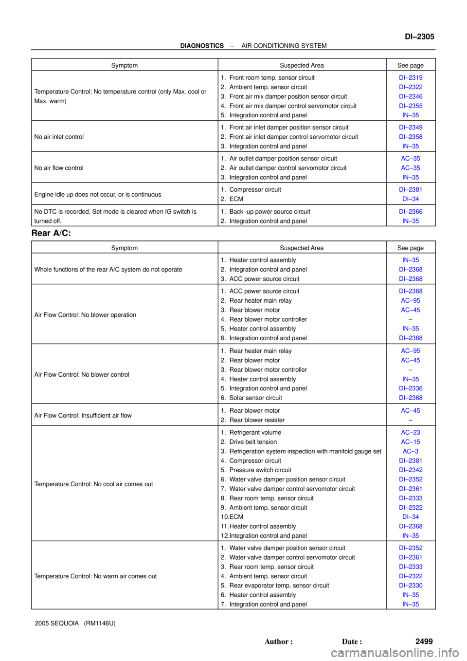
2005 SEQUOIA (RM1146U)Symptom
Suspected AreaSee page
Temperature Control: No temperature control (only Max. cool or
Max. warm)
1. Front room temp. sensor circuit
2. Ambient temp. sensor circuit
3. Front air mix damper position sensor circuit
4. Front air mix damper control servomotor circuit
5. Integration control and panelDI±2319
DI±2322
DI±2346
DI±2355
IN±35
No air inlet control
1. Front air inlet damper position sensor circuit
2. Front air inlet damper control servomotor circuit
3. Integration control and panelDI±2349
DI±2358
IN±35
No air flow control
1. Air outlet damper position sensor circuit
2. Air outlet damper control servomotor circuit
3. Integration control and panelAC±35
AC±35
IN±35
Engine idle up does not occur, or is continuous1. Compressor circuit
2. ECMDI±2381
DI±34
No DTC is recorded. Set mode is cleared when IG switch is
turned off.1. Back±up power source circuit
2. Integration control and panelDI±2366
IN±35
Rear A/C:
SymptomSuspected AreaSee page
Whole functions of the rear A/C system do not operate
1. Heater control assembly
2. Integration control and panel
3. ACC power source circuitIN±35
DI±2368
DI±2368
Air Flow Control: No blower operation
1. ACC power source circuit
2. Rear heater main relay
3. Rear blower motor
4. Rear blower motor controller
5. Heater control assembly
6. Integration control and panelDI±2368
AC±95
AC±45
±
IN±35
DI±2368
Air Flow Control: No blower control
1. Rear heater main relay
2. Rear blower motor
3. Rear blower motor controller
4. Heater control assembly
5. Integration control and panel
6. Solar sensor circuitAC±95
AC±45
±
IN±35
DI±2336
DI±2368
Air Flow Control: Insufficient air flow1. Rear blower motor
2. Rear blower resisterAC±45
±
Temperature Control: No cool air comes out
1. Refrigerant volume
2. Drive belt tension
3. Refrigeration system inspection with manifold gauge set
4. Compressor circuit
5. Pressure switch circuit
6. Water valve damper position sensor circuit
7. Water valve damper control servomotor circuit
8. Rear room temp. sensor circuit
9. Ambient temp. sensor circuit
10.ECM
11. Heater control assembly
12.Integration control and panelAC±23
AC±15
AC±3
DI±2381
DI±2342
DI±2352
DI±2361
DI±2333
DI±2322
DI±34
DI±2368
IN±35
Temperature Control: No warm air comes out
1. Water valve damper position sensor circuit
2. Water valve damper control servomotor circuit
3. Rear room temp. sensor circuit
4. Ambient temp. sensor circuit
5. Rear evaporator temp. sensor circuit
6. Heater control assembly
7. Integration control and panelDI±2352
DI±2361
DI±2333
DI±2322
DI±2330
IN±35
IN±35
Page 2518 of 4323
DI±2316
± DIAGNOSTICSAIR CONDITIONING SYSTEM
2510 Author�: Date�:
2005 SEQUOIA (RM1146U)
2. ACTIVE TEST
HINT:
Performing the ACTIVE TEST using the hand±held tester allows the relay, VSV, actuator and so on to oper-
ate without part removal. Performing the ACTIVE TEST as the first step of troubleshooting is one way to
shorten labor time.
(a) Connect the hand±held tester to the DLC3.
(b) Turn the ignition switch to the ON position.
(c) From the display on the tester, perform the ºACTIVE TESTº.
AIR CONDITIONING:
ItemTest Details / Display (Range)Diagnostic Note
BLOWER MOTORBlower motor / min.: 0 max.: 31±
AIR MIX DAMP±DAir mix damper (Driver side) / min.: ±14% max.: 113.5%±
A/I DAMP±LINEARAir inlet damper position (Linear) / min.: ±14% max.: 113.5%±
REAR BLOWERBlower motor (Rear) / min.: 0 max.: 31±
AIR MIX DAMP±RAir mix damper (Rear) / min.: ±14% max.: 113.5%±
A/C MAG CLUTCHA/C magnetic clutch relay / OFF, ON±
DEFOGGER RLY±RDefogger relay (Rear) / OFF, ON±
Page 2544 of 4323
I29011
ON (Below 1.0 W) Low pressure side High pressure side
OFF
(10 kW or higher)OFF
(10 kW or higher) (2.0 kgfVcm
2, 28 psi) (32.0 kgfVcm2, 455 psi) 196 KPa 3,140 KPa DI±2342
± DIAGNOSTICSAIR CONDITIONING SYSTEM
2536 Author�: Date�:
2005 SEQUOIA (RM1146U)
DTC 23 Pressure Switch Circuit
CIRCUIT DESCRIPTION
The pressure switch sends the appropriate signals to the A/C
amplifier when the A/C refrigerant pressure drops too low or
rises too high. When the A/C amplifier receives these signals,
it outputs signals through the A/C amplifier to turn the magnet
clutch relay off and turns the magnetic clutch off.
DTC No.Detection ItemTrouble Area
23
�Open in pressure sensor circuit.
�Abnormal refrigerant pressure.
below 196 kPa (2.0 kg/cm
2, 28 psi)
over 3,140 kPa (32.0 kgf/cm2, 455 psi)
�Pressure switch
�Harness or connector between pressure switch and integra-
tion control and panel
�Refrigerant pipe line
�Integration control and panel
DI3FD±09
Page 2576 of 4323
Duty Ratio =A + BA
x 100 (%)
ON
OFFA
B
1 cycle
Blower Level
0
Si duty (%)
LO M1M2HI
29.2
42.4 55.5100
M3
70.9
I15873
Integration Control
and Panel
BLW From
Heater Relay
W±B
IGAGND
VM
SI J18
J/C+B
3
4L±B
1
G±B
I19
24 B3
Blower
Motor (Front)
12 L±WL±B
L±B
B4
Blower Motor
Linear Controller DI±2374
± DIAGNOSTICSAIR CONDITIONING SYSTEM
2568 Author�: Date�:
2005 SEQUOIA (RM1146U)
Blower Motor Circuit (Front A/C)
CIRCUIT DESCRIPTION
The blower motor is operated by signals from the integration
control and panel. Blower motor speed signals are transmitted
by changes in the Duty Ratio.
Duty Ratio
The duty ratio is the ratio of the period of continuity in one cycle.
For example, if A is the period of continuity in one cycle, and B
is the period of non±continuity, then.
WIRING DIAGRAM
DI7SL±08