Page 3556 of 4323
BE0FY±32
I28423
Horn
Horn Switch
Engine Room J/B
� HORN Relay
� HORN Fuse
BE±144
± BODY ELECTRICALHORN SYSTEM
3548 Author�: Date�:
2005 SEQUOIA (RM1146U)
HORN SYSTEM
LOCATION
Page 3558 of 4323
I01200
2 1
35
2 5
1 3
BE±146
± BODY ELECTRICALHORN SYSTEM
3550 Author�: Date�:
2005 SEQUOIA (RM1146U)
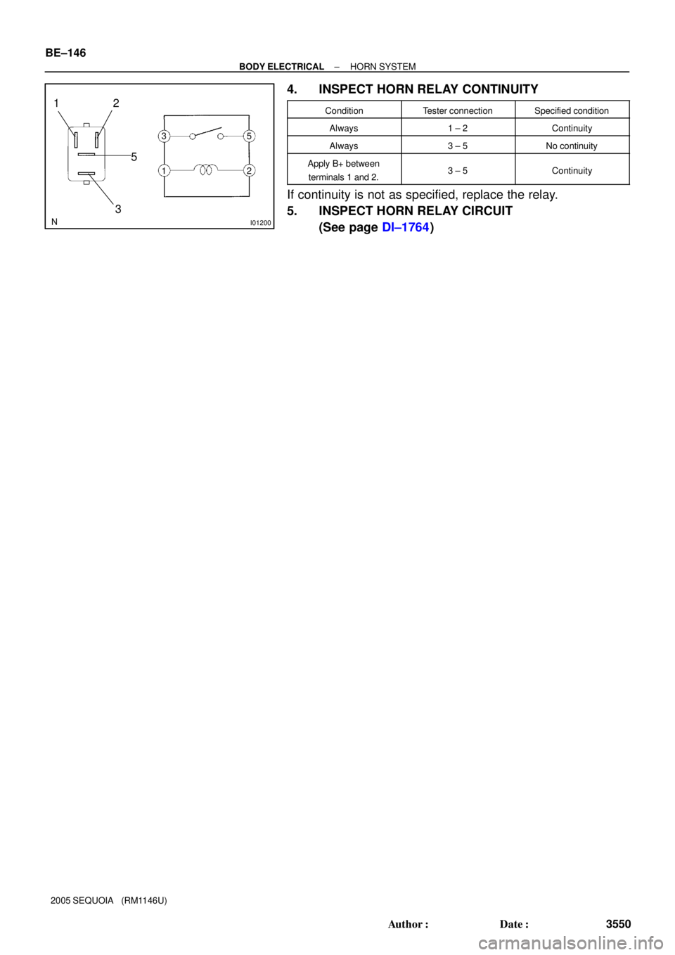
4. INSPECT HORN RELAY CONTINUITY
ConditionTester connectionSpecified condition
Always1 ± 2Continuity
Always3 ± 5No continuity
Apply B+ between
terminals 1 and 2.3 ± 5Continuity
If continuity is not as specified, replace the relay.
5. INSPECT HORN RELAY CIRCUIT
(See page DI±1764)
Page 3559 of 4323
BE26G±04
I28424
Engine Room J/B
� TOWING Fuse
Trailer Socket
Towing Converter Relay
(Located inside of the quarter trim panel LH)
Engine Room R/B No. 3
� BATT CHARGE Relay
� TOWING TAIL Relay
� TOWING BRK Fuse
� TOWING TAIL Fuse
Brake Controller
(Located inside of the cowl side trim board LH)
± BODY ELECTRICALTRAILER TOWING
BE±147
3551 Author�: Date�:
2005 SEQUOIA (RM1146U)
TRAILER TOWING
LOCATION
Page 3561 of 4323

2. Trailer Socket 7 Pin Type:
INSPECT BRAKE CONTROLLER")
I24379
Wire Harness Side:
I18635
1
2 34
5
I18635
1
2 34
5
± BODY ELECTRICALTRAILER TOWING
BE±149
3553 Author�: Date�:
2005 SEQUOIA (RM1146U)
2. Trailer Socket 7 Pin Type:
INSPECT BRAKE CONTROLLER CIRCUIT
Remove the brake controller with the connector still connected
and inspect the wire harness side connector from the back side,
as shown in the table below.
Tester connectionConditionSpecified condition
1 ± 3Stop light switch ON (Brake pedal depressed)10 ± 14 V
1 ± 3Stop light switch OFF (Brake pedal released)0 V
2 ± 3Always10 ± 14 V
3 ± 4Stop light switch ON (Brake pedal depressed)10 ± 14 V
3 ± 4Stop light switch OFF (Brake pedal released)0 V
3 ± 5Light control switch TAIL or HEAD10 ± 14 V
3 ± 5Light control switch OFF0 V
If the circuit is not as specified, inspect the circuit connected to
other parts.
3. INSPECT TOWING TAIL RELAY CONTINUITY
ConditionTester connectionSpecified condition
Always1 ± 2Continuity
Always3 ± 5No continuity
Apply B+ between
terminals 1 and 2.3 ± 5Continuity
If continuity is not as specified, replace the relay.
4. INSPECT BATT CHARGE RELAY CIRCUIT
ConditionTester connectionSpecified condition
Always1 ± 2Continuity
Always3 ± 5No continuity
Apply B+ between
terminals 1 and 2.3 ± 5Continuity
If continuity is not as specified, replace the relay.
Page 3748 of 4323
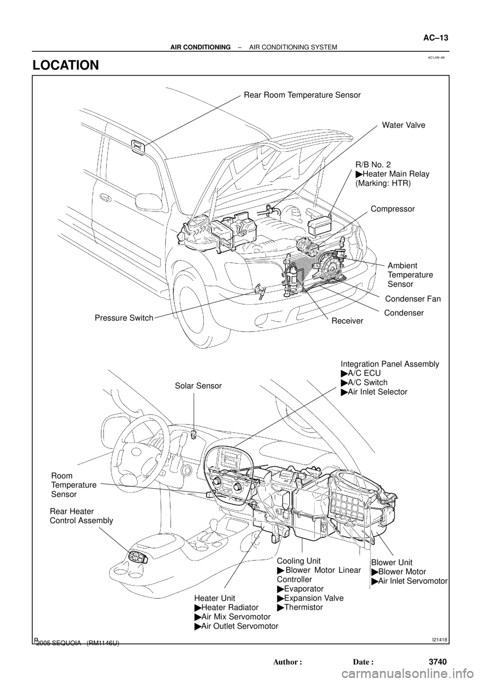
AC1JW±06
I21418
R/B No. 2
� Heater Main Relay
(Marking: HTR)
Compressor
Condenser
Receiver Pressure Switch
Integration Panel Assembly
� A/C ECU
� A/C Switch
� Air Inlet Selector
Heater Unit
� Heater Radiator
� Air Mix Servomotor
� Air Outlet Servomotor
Cooling Unit
� Blower Motor Linear
Controller
� Evaporator
� Expansion Valve
� ThermistorBlower Unit
� Blower Motor
� Air Inlet Servomotor
Water Valve
Rear Heater
Control Assembly
Condenser Fan
Ambient
Temperature
Sensor
Solar Sensor
Room
Temperature
Sensor
Rear Room Temperature Sensor
± AIR CONDITIONINGAIR CONDITIONING SYSTEM
AC±13
3740 Author�: Date�:
2005 SEQUOIA (RM1146U)
LOCATION
Page 3830 of 4323
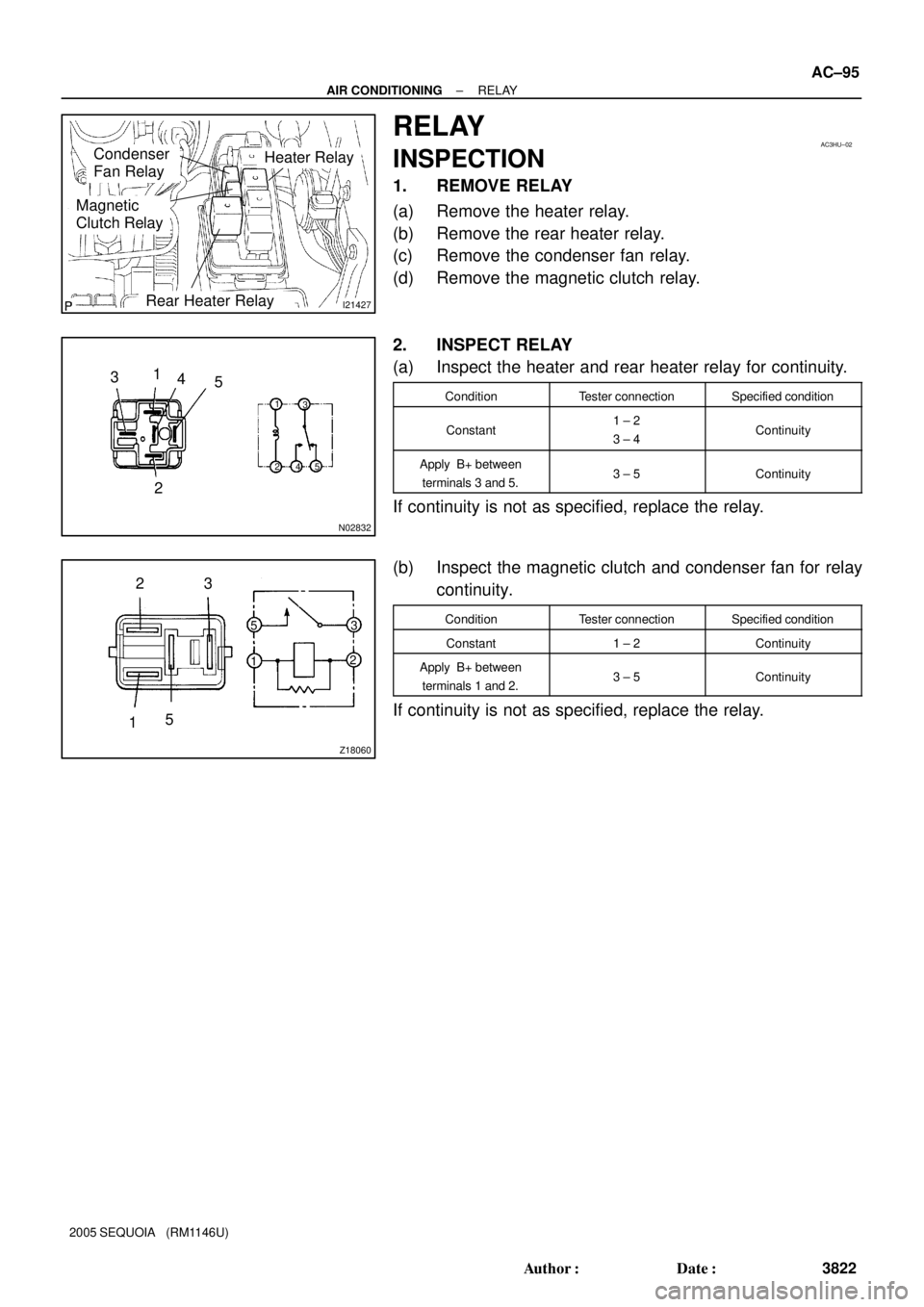
I21427
Heater RelayCondenser
Fan Relay
Magnetic
Clutch Relay
Rear Heater Relay
AC3HU±02
N02832
1
2 3
5
1
23
5
4
4
Z18060
23
15
5
13
2
± AIR CONDITIONINGRELAY
AC±95
3822 Author�: Date�:
2005 SEQUOIA (RM1146U)
RELAY
INSPECTION
1. REMOVE RELAY
(a) Remove the heater relay.
(b) Remove the rear heater relay.
(c) Remove the condenser fan relay.
(d) Remove the magnetic clutch relay.
2. INSPECT RELAY
(a) Inspect the heater and rear heater relay for continuity.
ConditionTester connectionSpecified condition
Constant1 ± 2
3 ± 4Continuity
Apply B+ between
terminals 3 and 5.3 ± 5Continuity
If continuity is not as specified, replace the relay.
(b) Inspect the magnetic clutch and condenser fan for relay
continuity.
ConditionTester connectionSpecified condition
Constant1 ± 2Continuity
Apply B+ between
terminals 1 and 2.3 ± 5Continuity
If continuity is not as specified, replace the relay.
Page 3831 of 4323

CONDENSER FAN
ON±VEHICLE INSPECTION
1. INSPECT CONDENSER FAN OPERATION
Inspect the fan opera")
AC1LZ±05
I21428
1 2
AC±96
± AIR CONDITIONINGCONDENSER FAN
3823 Author�: Date�:
2005 SEQUOIA (RM1146U)
CONDENSER FAN
ON±VEHICLE INSPECTION
1. INSPECT CONDENSER FAN OPERATION
Inspect the fan operation under the following conditions, as
shown in the chart.
Test conditions:
�Start engine
�Blower speed control switch position ºHIº
�Temperature control dial at ºCOOLº position
�Set manifold gauge set
�A/C switch ON
ConditionFan operation (Fan speed)
Refrigerant pressure is less than
1,520 kPa (15.5 kgf/cm2, 220 psi)OFF
Refrigerant pressure is 1,520 kPa
(15.5 kgf/cm2, 220 psi) or aboveRotate
If operation is not as specified, proceed to the next inspection.
2. INSPECT CONDENSER FAN MOTOR OPERATION
(a) Disconnect the fan connector.
(b) Connect the battery and ammeter.
(c) Check that the fan rotates smoothly, and then check the
reading on the ammeter.
Specified amperage: 9.2 to 11.0 A at 20°C (68°F)
If operation is not as specified, replace the fan motor.
If operation is as specified, check the pressure switch, cooling
fan relays and water temp. switch.
Page 4233 of 4323

374
2005 SEQUOIA from Aug. 04 Prod. (OM34424U)
4±pin connector
7±pin connector
TRAILER LIGHTS
�Your vehicle is equipped with a wire
harness stored in the rear end under
bod")
05_SEQUOIA_U (L/O 0408)
374
2005 SEQUOIA from Aug. '04 Prod. (OM34424U)
4±pin connector
7±pin connector
TRAILER LIGHTS
�Your vehicle is equipped with a wire
harness stored in the rear end under
body. Some models are fitted with a
socket for trailer lights under the rear
bumper. Use either of them to connect
and operate the trailer lights. However,
the trailer lights must comply with fed-
eral, state/provincial and local regula-
tions. See your local recreational ve-
hicle dealer or rental agency for the
correct type of wiring and relays for
your trailer. Check for correct operation
of the turn signals and stop lights each
time you hitch up. Direct splicing may
damage your vehicle's electrical system
and cause a malfunction of your lights.
7±pin connector (with towing pack-
age)ÐThis can be also connected to
the trailer brake and trailer sub battery.NOTICE
Do not tow a trailer with (1) total tail
light electric power consumption of
over 93 W or (2) total turn and stop
light electric power consumption of
over 54 W.
Ex. (1) Tail lights
" under 9.3 W
(SAE J573 No.69)
� 10
bulbs
(2) Turn/stop lights
" under 27
W (SAE J573 No.1157)
� 4
bulbs (left 2, right 2)
BREAK±IN SCHEDULE
�Toyota recommends that you do not
tow a trailer with a new vehicle or a
vehicle with any new power train com-
ponent (engine, transmission, differen-
tial, wheel bearing, etc.) for the first
3200 km (2000 miles) of driving.