Page 1894 of 4323

DI±1692
± DIAGNOSTICSBODY CONTROL SYSTEM
1886 Author�: Date�:
2005 SEQUOIA (RM1146U) FFOG ± GND1
(B6±13 ± B6±6)
G±B ± W±BFog light switch signalHeadlight dimmer switch LOW,
Fog light switch ON10 to 14 V
DIM (*1) ± GND1
(B7±17 ± B6±6)R ± W±BDIMMER relay signalIgnition switch OFFBelow 1 V
DIM (*1) ± GND1
(B7±17 ± B6±6)R ± W±BDIMMER relay signalIgnition switch ON10 to 14 V
H±ON (*1) ± GND1
(B7±16 ± B6±6)R±W ± W±BDRL No.4 relay signalIgnition switch OFFBelow 1 V
H±ON (*1) ± GND1
(B7±16 ± B6±6)R±W ± W±BDRL No.4 relay signalIgnition switch ON10 to 14 V
HIND (*1) ± GND1
(B5±18 ± B6±6)GR±L ± W±BHi±beam indicator light
signalIgnition switch OFFBelow 1 V
HIND (*1) ± GND1
(B5±18 ± B6±6)GR±L ± W±BHi±beam indicator light
signalIgnition switch ON10 to 14 V
A (*3) ± GND1
(B6±10 ± B6±6)L±R ± W±BLight control switch
(AUTO)Light control switch OFFBelow 1 V
A (*3) ± GND1
(B6±10 ± B6±6)L±R ± W±BLight control switch
(AUTO)Light control switch AUTO10 to 14 V
MIRE ± GND1
(B5±28 ± B6±6)LG±B ± W±BRemote control mirror
switch (Ground)AlwaysBelow 1 V
MIRS ± GND1
(B5±29 ± B6±6)P±L ± W±BRemote control mirror
switch (IG)Ignition switch ON10 to 14 V
MIRS ± GND1
(B5±29 ± B6±6)P±L ± W±BRemote control mirror
switch (IG)Ignition switch ON,
Mirror switch L or R position se-
lected
Below 1 V
MIRB ± GND1
(B5±30 ± B6±6)G±B ± W±BRemote control mirror
switch (Battery)Always10 to 14 V
S+B ± GND1
(B6±1 ± B6±6)W±L ± W±BBatteryAlways10 to 14 V
PWS ± GND1
(B6±21 ± B6±6)R±L ± W±BBack door power win-
dow switch (Ground)Ignition switch ONBelow 1 V
PWS ± GND1
(B6±21 ± B6±6)R±L ± W±BBack door power win-
dow switch (Ground)Ignition switch ON,
Back door power window switch
operated
10 to 14 V
M2 (*4) ± GND1
(B6±22 ± B6±6)G ± W±BDriving position
memory switch (M2)Ignition switch ON10 to 14 V
M2 (*4) ± GND1
(B6±22 ± B6±6)G ± W±BDriving position
memory switch (M2)Ignition switch ON,
Driving position memory switch
M2 button pushed
Below 1 V
M1 (*4) ± GND1
(B6±23 ± B6±6)L±Y ± W±BDriving position
memory switch (M1)Ignition switch ON10 to 14 V
M1 (*4) ± GND1
(B6±23 ± B6±6)L±Y ± W±BDriving position
memory switch (M1)Ignition switch ON,
Driving position memory switch
M1 button pushed
Below 1 V
MM (*4) ± GND1
(B6±24 ± B6±6)L ± W±BDriving position
memory switch (SET)Ignition switch ON10 to 14 V
MM (*4) ± GND1
(B6±24 ± B6±6)L ± W±BDriving position
memory switch (SET)Ignition switch ON,
Driving position memory switch
SET button pushed
Below 1 V
Page 1899 of 4323

± DIAGNOSTICSBODY CONTROL SYSTEM
DI±1697
1891 Author�: Date�:
2005 SEQUOIA (RM1146U)DISP EX ON SEN
Display extinction luminous inten-
sity/NORMAL, DARK2, DARK1,
LIGHT1 or LIGHT2Customized condition will be dis-
played±
DISP EX OFF SEN
Display extinction release lumi-
nous intensity/NORMAL, DARK2,
DARK1, LIGHT1 or LIGHT2Customized condition will be dis-
played±
2. ACTIVE TEST
HINT:
Performing the ACTIVE TEST using the hand±held tester allows the relays, actuators and so on to operate
without parts removal. Performing the ACTIVE TEST as a first step of troubleshooting is one of the methods
to shorten labor time.
It is possible to display the DATE LIST during the ACTIVE TEST.
(a) Connect the hand±held tester to the DLC3.
(b) Turn the ignition switch ON.
(c) According to the display on the tester, perform the ºACTIVE TESTº.
BODY ECU:
ItemTest DetailsDiagnostic Note
SECURITY INDICTurn security indicator light ON/OFF±
SECURITY HORNTurn theft horn ON/OFFThis test is available only for vehicles equipped
with security horn.
BUZZ CONT SOUNDWireless buzzer continuous sound ON/OFF±
BUZZ RESP SOUNDTurn wireless buzzer ON/OFFTurn volume to MAX if it is a wireless buzzer
equipped vehicle.
HEAD LIGHTHeadlight relay ON/OFF±
TAIL LIGHTTaillight ON/OFF±
ILLUMI OUTPUTIlluminated entry system ON/OFFIG is ON, E/G is stopped and light control SW is
OFF.
ALL COURTESYDOOR indicator light ON/OFF±
VEHICLE HORNTurn vehicle horn ON/OFF±
RL P/W UP/DOWNRear left passenger power window DOWN/UPCaution: This test causes vehicle parts to move.
Watch your hands and feet.
RR P/W UP/DOWNRear right passenger power window DOWN/UPCaution: This test causes vehicle parts to move.
Watch your hands and feet.
DOOR LOCKDoor lock LOCK/UNLOCKAll doors are closed.
Page 1900 of 4323

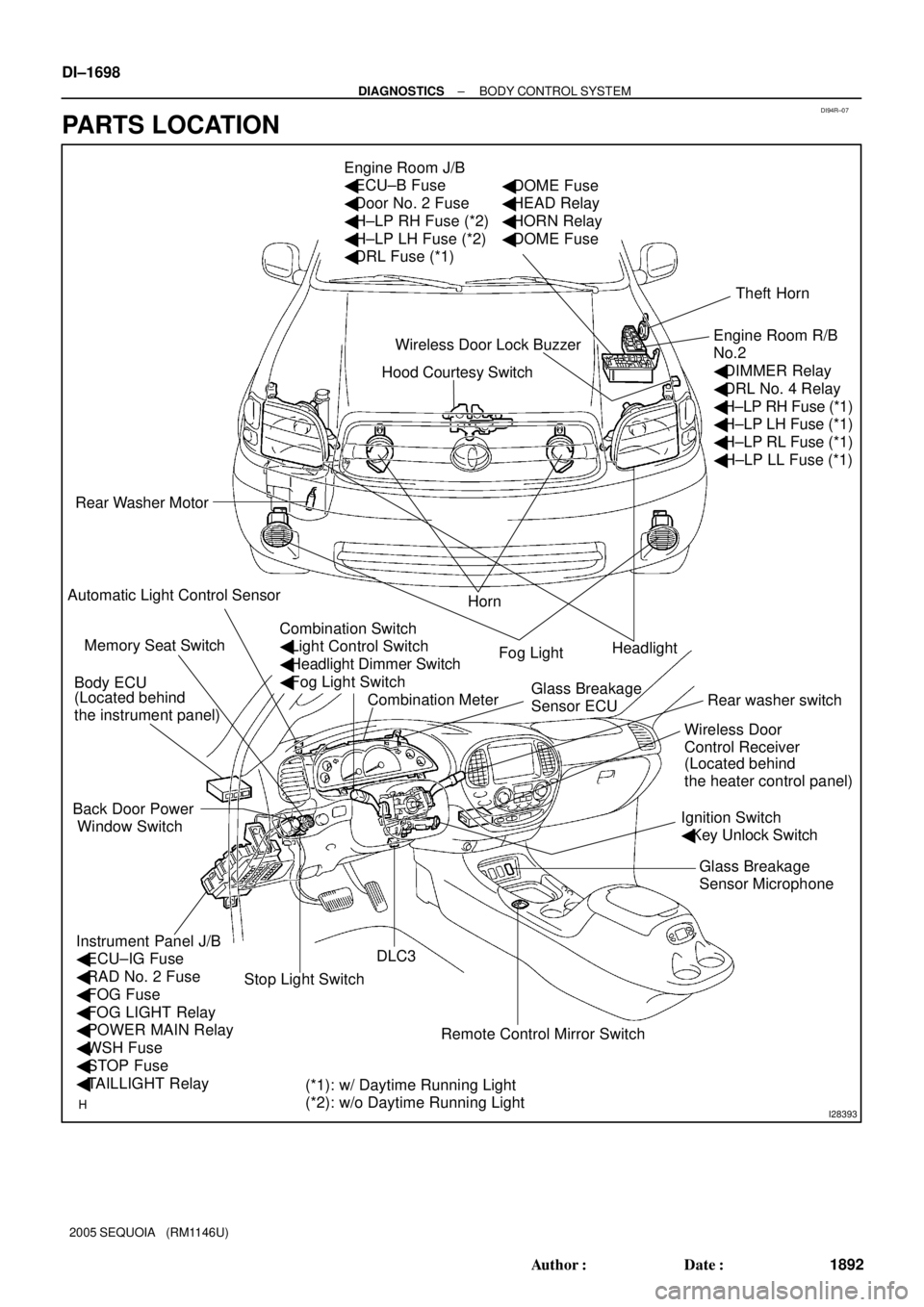
DI94R±07
I28393
Hood Courtesy Switch Engine Room J/B
� ECU±B Fuse
� Door No. 2 Fuse
� H±LP RH Fuse (*2)
� H±LP LH Fuse (*2)
� DRL Fuse (*1)
Rear Washer Motor
Horn
Headlight
Rear washer switch
Ignition Switch
� Key Unlock Switch
DLC3 Body ECU
Instrument Panel J/B
� ECU±IG Fuse
� RAD No. 2 Fuse
� FOG Fuse
� FOG LIGHT Relay
� POWER MAIN Relay
� WSH Fuse
� STOP Fuse
� TAILLIGHT Relay Back Door Power
Window SwitchTheft Horn
Engine Room R/B
No.2
� DIMMER Relay
� DRL No. 4 Relay
� H±LP RH Fuse (*1)
� H±LP LH Fuse (*1)
� H±LP RL Fuse (*1)
� H±LP LL Fuse (*1)
Fog Light
Wireless Door
Control Receiver Wireless Door Lock Buzzer
Combination Meter Memory Seat Switch
(*1): w/ Daytime Running Light
(*2): w/o Daytime Running Light (Located behind
the instrument panel)
(Located behind
the heater control panel)
� DOME Fuse
� HEAD Relay
� HORN Relay
� DOME Fuse
Automatic Light Control Sensor
Stop Light Switch
Remote Control Mirror SwitchGlass Breakage
Sensor Microphone Glass Breakage
Sensor ECU
Combination Switch
� Light Control Switch
� Headlight Dimmer Switch
� Fog Light Switch DI±1698
± DIAGNOSTICSBODY CONTROL SYSTEM
1892 Author�: Date�:
2005 SEQUOIA (RM1146U)
PARTS LOCATION
Page 1908 of 4323

I24351
Body ECU
11 3
21 5
B 5W
1G TAILLIGHT Relay
To Taillight
F10
Fusible Link BlockLG
B7
ALTTRLY 2 1L
81
BatteryInstrument Panel J/B
LG
DDJ/9
J/C DI±1706
± DIAGNOSTICSBODY CONTROL SYSTEM
1900 Author�: Date�:
2005 SEQUOIA (RM1146U)
Taillight Relay Circuit
CIRCUIT DESCRIPTION
TAILLIGHT relay will be ºONº by operating the light control switch. The transistor which activates the tail light
relay has two sorts: one is activated by the light control switch for fail safe and the other is activated by CPU.
When the theft deterrent system is activated, it causes the transistor in the ECU to switch ON and OFF at
approximately 0.4 sec. intervals. This switches the TAILLIGHT relay ON and OFF, and thus flashing the tail-
lights (See the wiring diagram below).
In this condition, if any of the following operations is done, the transistor in the ECU goes OFF and the TAIL-
LIGHT relay switches OFF, and thus stopping the taillights flashing:
(1) Unlock the front LH or RH door with a key.
(2) Turn the ignition switch to ACC or ON position.
(3) Unlock the doors with the wireless door lock control system.
(4) Wait for approximately 60 seconds.
WIRING DIAGRAM
DI6QY±15
Page 1909 of 4323

± DIAGNOSTICSBODY CONTROL SYSTEM
DI±1707
1901 Author�: Date�:
2005 SEQUOIA (RM1146U)
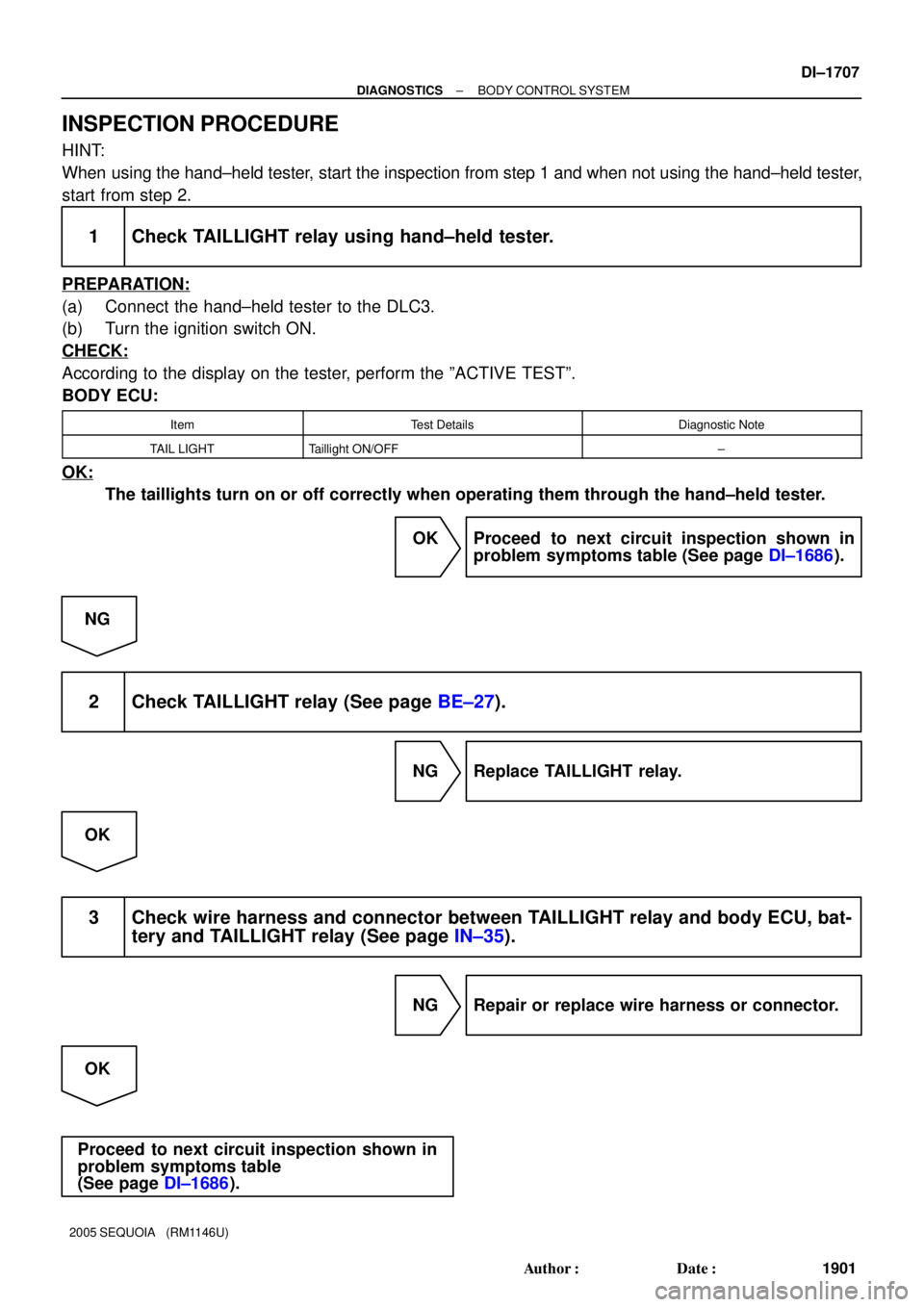
INSPECTION PROCEDURE
HINT:
When using the hand±held tester, start the inspection from step 1 and when not using the hand±held tester,
start from step 2.
1 Check TAILLIGHT relay using hand±held tester.
PREPARATION:
(a) Connect the hand±held tester to the DLC3.
(b) Turn the ignition switch ON.
CHECK:
According to the display on the tester, perform the ºACTIVE TESTº.
BODY ECU:
ItemTest DetailsDiagnostic Note
TAIL LIGHTTaillight ON/OFF±
OK:
The taillights turn on or off correctly when operating them through the hand±held tester.
OK Proceed to next circuit inspection shown in
problem symptoms table (See page DI±1686).
NG
2 Check TAILLIGHT relay (See page BE±27).
NG Replace TAILLIGHT relay.
OK
3 Check wire harness and connector between TAILLIGHT relay and body ECU, bat-
tery and TAILLIGHT relay (See page IN±35).
NG Repair or replace wire harness or connector.
OK
Proceed to next circuit inspection shown in
problem symptoms table
(See page DI±1686).
Page 1910 of 4323

I24144
Body ECU
MAINEngine Room J/B
HEAD Relay
Instrument Panel J/B
Battery
LG±R 2D
B12FL
R±W
12 532F
2G
2C
B7 1G 1JL
R±L
R±L
HRLY 8
6
1
6
1
2
(*1): w/ Daytime Running Light
(*2): w/o Daytime Running LightLG±R69 8 To Headlight RH To Headlight LH To DRL No.4 Relay To DIMMER Relay To DIMMER Relay
B 4
5 F10
FL Block(*2) (*2) (*1)
(*1)
(*1)
H±LP RH (*2)
DRL (*1)
H±LP LH (*2)
(*1) DI±1708
± DIAGNOSTICSBODY CONTROL SYSTEM
1902 Author�: Date�:
2005 SEQUOIA (RM1146U)
Headlight Relay Circuit
CIRCUIT DESCRIPTION
HEAD relay will be ºONº by operating the light control switch. The transistor which activates the HEAD relay
has two sorts: one is activated by the light control switch for fail safe and the other is activated by CPU. The
one that is activated by CPU prevents the headlight from turning off at the time of trouble with the other sys-
tem in the automatic operation circuit.
When the theft deterrent system is activated, it causes the transistor in the ECU to switch ON and OFF at
approximately 0.25 sec. intervals. This switches the HEAD relay ON and OFF, and thus flashing the head-
lights (See the wiring diagram below).
In this condition, if any of the following operations is done, the transistor in the ECU goes OFF and the HEAD
control relay switches OFF, and thus stopping the headlights flashing:
(1) Unlock the front LH or RH door with a key.
(2) Turn the ignition switch to ACC or ON position.
(3) Unlock the doors with the wireless door lock control system.
(4) Wait for approximately 60 seconds.
WIRING DIAGRAM
DI5VQ±14
Page 1911 of 4323

± DIAGNOSTICSBODY CONTROL SYSTEM
DI±1709
1903 Author�: Date�:
2005 SEQUOIA (RM1146U)
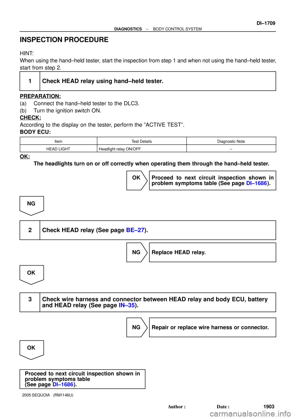
INSPECTION PROCEDURE
HINT:
When using the hand±held tester, start the inspection from step 1 and when not using the hand±held tester,
start from step 2.
1 Check HEAD relay using hand±held tester.
PREPARATION:
(a) Connect the hand±held tester to the DLC3.
(b) Turn the ignition switch ON.
CHECK:
According to the display on the tester, perform the ºACTIVE TESTº.
BODY ECU:
ItemTest DetailsDiagnostic Note
HEAD LIGHTHeadlight relay ON/OFF±
OK:
The headlights turn on or off correctly when operating them through the hand±held tester.
OK Proceed to next circuit inspection shown in
problem symptoms table (See page DI±1686).
NG
2 Check HEAD relay (See page BE±27).
NG Replace HEAD relay.
OK
3 Check wire harness and connector between HEAD relay and body ECU, battery
and HEAD relay (See page IN±35).
NG Repair or replace wire harness or connector.
OK
Proceed to next circuit inspection shown in
problem symptoms table
(See page DI±1686).
Page 1912 of 4323
I28516
J5
J/CBody ECU
FFOG J50
J/C J3
J/C
5 Instrument Panel J/B
From DIMMER Relay (*1) FOG LIGHT Relay
FOG
1K7
1B9
1J10 1L1
3
1 2 D
D
D
1
2F2
Front Fog
Light RH
W±B
B 1
2P
W±B
EDIGALTF10
FL Block 8
5
B
BatteryR±W
C8 Combination Switch
� Fog Light Switch
B613
G±B
10
LFG BFG 11 P
F1
Front Fog
Light LH
G±W (*1)
Y±R (*2) WP
A
(*1): w/ Daytime Running Light
(*2): w/o Daytime Running LightB
J2
J/C B
BW±B
J18
J/C W±B W±B
IL1
From Headlight (*2) 16
A DI±1710
± DIAGNOSTICSBODY CONTROL SYSTEM
1904 Author�: Date�:
2005 SEQUOIA (RM1146U)
Front fog light relay and switch circuit
CIRCUIT DESCRIPTION
The fog light switch is built into the combination switch.
Turning the fog light switch ON supplies power to terminal FFOG of the body ECU.
The fog lights come on when the FOG light relay is turned on.
WIRING DIAGRAM
DI6U4±14