Page 1988 of 4323

DI±1786
± DIAGNOSTICSDRIVER DOOR CONTROL SYSTEM
1980 Author�: Date�:
2005 SEQUOIA (RM1146U)
*1: When the ignition key is not in the key cylinder and the back door is locked, turning and holding the key
in the back door key cylinder in the lock position for 1.5 seconds or more activates the driver door ECU to
operate the power window motor and close the power window.
Similarly, turning and holding the key in the back door key cylinder in the unlock position for 1.5 seconds or
more when the back door is unlocked will open the power window.
ItemMeasurement Item/Display (Range)Normal ConditionDiagnostic Note
MIR POS SEN VVertical mirror position/Min.: 0, Max.: 5Within range from 0 to 5 V±
MIR POS SEN HVertical mirror position/Min.: 0, Max.: 5Within range from 0 to 5 V±
2. ACTIVE TEST
HINT:
Performing the ACTIVE TEST using the hand±held tester allows the relay, actuator and so on to operate
without removal. Performing the ACTIVE TEST as the first step of troubleshooting is one of the methods to
shorten labor time.
It is possible to display the DATA LIST during the ACTIVE TEST.
(a) Connect the hand±held tester to the DLC3.
(b) Turn the ignition switch ON.
(c) According to the display on the tester, perform the ACTIVE TEST.
D±DOOR:
ItemTest DetailsDiagnostic Note
P/W UP/DOWNDrive the P/W Motor UP/DOWN
During this ACTIVE TEST, jam protection, caught
detection can be monitored.
(Refer to the DATA LIST for details)
MIRR UP/DOWNMirror motor vertical operation UP/OFF/DOWN±
MIRR RIGHT/LEFTMirror motor horizontal operation RIGHT/OFF/
LEFT±
Page 2007 of 4323

I24364
D22
Driver Door ECU P4 Power Window
Control SW Rear RH
F18
Front Passenger Door ECU F10
Fusible Link Block
P3 Power Window Control
SW Rear LHE
B
L±O
5 W±B
PWR No. 4
R±L
WLSW U
D 3
5
24
BC1
A
J46L±O L±O 13
BC1 W±B
U
D5
2GR
2 1
BL±Y5
BA1L±YG
J30
L±Y
7
1G
8
1F
16
1F PWR No. 3 3
5
21 1
1L
9
1F
E
J6E
J7
E
J67
R±L
R±L
R±L
II1
LSW W±B
Battery
J8
J/CIE A W±B
BKW
85
B
BA1 13
W±B
BH ALTGR
2
1
3E
Power Main Relay
Instrument Panel J/B
J/C P9
Power
Window
Motor
Rear
RH P8
Power
Window
Motor
Rear
LH
7 4
5 N J/C
J/C
E J29
J47
± DIAGNOSTICSDRIVER DOOR CONTROL SYSTEM
DI±1805
1999 Author�: Date�:
2005 SEQUOIA (RM1146U)
Window lock switch circuit
CIRCUIT DESCRIPTION
The window lock switch circuit can be checked using the DTC check (refer to DI±1904).
The window lock switch is built in the driver door ECU. Voltage applied to the WLSW terminal of the driver
door ECU is shut off when the window lock switch is turned to the LOCK position. Thus the power main relay
stops power supply to the other power window control switches.
WIRING DIAGRAM
DI1PE±15
Page 2008 of 4323

DI±1806
± DIAGNOSTICSDRIVER DOOR CONTROL SYSTEM
2000 Author�: Date�:
2005 SEQUOIA (RM1146U)
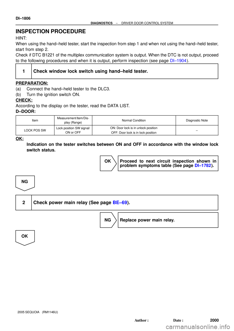
INSPECTION PROCEDURE
HINT:
When using the hand±held tester, start the inspection from step 1 and when not using the hand±held tester,
start from step 2.
Check if DTC B1221 of the multiplex communication system is output. When the DTC is not output, proceed
to the following procedures and when it is output, perform inspection (see page DI±1904).
1 Check window lock switch using hand±held tester.
PREPARATION:
(a) Connect the hand±held tester to the DLC3.
(b) Turn the ignition switch ON.
CHECK:
According to the display on the tester, read the DATA LIST.
D±DOOR:
ItemMeasurement Item/Dis-
play (Range)Normal ConditionDiagnostic Note
LOCK POS SWLock position SW signal/
ON or OFFON: Door lock is in unlock position
OFF: Door lock is in lock position±
OK:
Indication on the tester switches between ON and OFF in accordance with the window lock
switch status.
OK Proceed to next circuit inspection shown in
problem symptoms table (See page DI±1782).
NG
2 Check power main relay (See page BE±69).
NG Replace power main relay.
OK
Page 2026 of 4323
DI±1824
± DIAGNOSTICSPASSENGER DOOR CONTROL SYSTEM
2018 Author�: Date�:
2005 SEQUOIA (RM1146U)
2. ACTIVE TEST
HINT:
Performing the ACTIVE TEST using the hand±held tester allows the relay, VSV, actuator and so on to oper-
ate without parts removal. Performing the ACTIVE TEST as the first step of troubleshooting is one of the
methods to shorten labor time.
It is possible to display the DATA LIST during the ACTIVE TEST.
(a) Connect the hand±held tester to the DLC3.
(b) Turn the ignition switch ON.
(c) According to the display on the tester, perform the ACTIVE TEST.
P±DOOR:
ItemTest DetailsDiagnostic Note
P/W UP/DOWNDrive the P/W Motor UP/DOWN
During this ACTIVE TEST, jam protection,
caught detection can be monitored.
(Refer to the DATA LIST for details)
MIRR UP/DOWNMirror motor vertical operation UP/OFF/DOWN±
MIRR RIGHT/LEFTMirror motor horizontal operation RIGHT/OFF/
LEFT±
Page 2045 of 4323
I28443
F18
Front Passenger Door ECUD22
Driver Door ECU
WLSW 7
R±L E
J7 J/C
E
J6
R±L
R±LII15
LSW7
± DIAGNOSTICSPASSENGER DOOR CONTROL SYSTEM
DI±1843
2037 Author�: Date�:
2005 SEQUOIA (RM1146U)
Window lock switch circuit
CIRCUIT DESCRIPTION
The power window lock switch circuit can be checked using the DTC check (refer to DI±1904).
The window lock switch is built in the passenger door ECU. Voltage applied to the LSW terminal of the pas-
senger door ECU is shut off when the window lock switch is turned to the LOCK position. The power main
relay stops power supply to the other power window control switches.
WIRING DIAGRAM
DI1PE±16
Page 2061 of 4323

± DIAGNOSTICSBACK DOOR CONTROL SYSTEM
DI±1859
2053 Author�: Date�:
2005 SEQUOIA (RM1146U)
*1: When the ignition key is not in the key cylinder and the back door is locked, turning and holding the back
door key in the lock position for 1.5 seconds or more activates the back door ECU to operate the power win-
dow motor and close the power window.
Similarly, turning and holding the back door key in the unlock position for 1.5 seconds or more when the back
door is unlocked will open the power window.
2. ACTIVE TEST
HINT:
Performing the ACTIVE TEST using the hand±held tester allows the relay, VSV, actuator and so on to oper-
ate without parts removal. Performing the ACTIVE TEST as a first step of troubleshooting is one of the meth-
ods to shorten labor time.
It is possible to display the DATA LIST during the ACTIVE TEST.
(a) Connect the hand±held tester to the DLC3.
(b) Turn the ignition switch ON.
(c) According to the display on the tester, perform the ACTIVE TEST.
BACK±DOOR:
ItemTest detailsDiagnostic note
P/W UP/DOWNOperate the back door power window motor UP/
DOWNDuring this ACTIVE TEST, jam protection caught
detection can be monitored.
(Refer to the DATA LIST for details)
DOOR LOCKOperate the door lock motor at rear door LOCK/
UNLOCK±
REAR WIPEROperate the rear wiper motor ON/OFF±
Page 2169 of 4323

DID9Q±01
± DIAGNOSTICSAUDIO SYSTEM
DI±1967
2161 Author�: Date�:
2005 SEQUOIA (RM1146U)
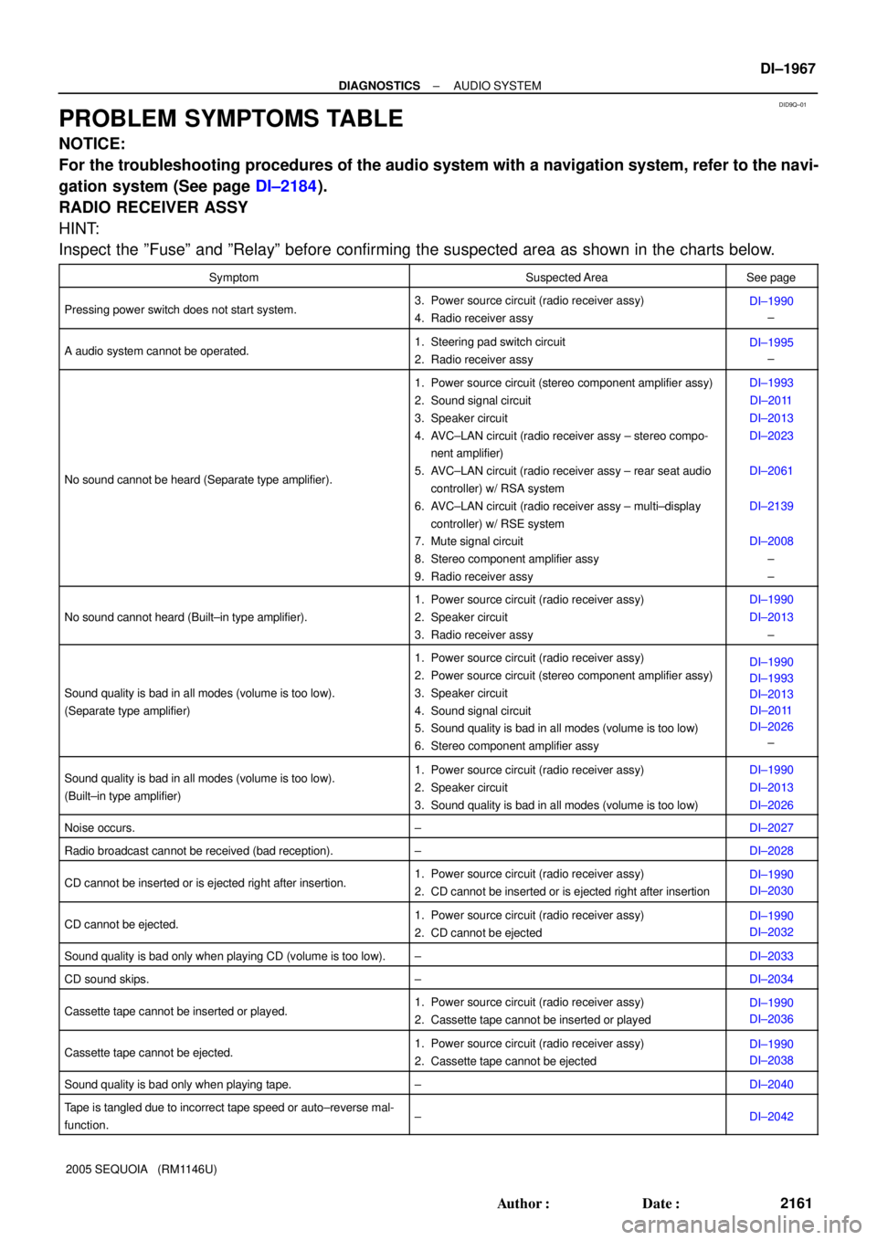
PROBLEM SYMPTOMS TABLE
NOTICE:
For the troubleshooting procedures of the audio system with a navigation system, refer to the navi-
gation system (See page DI±2184).
RADIO RECEIVER ASSY
HINT:
Inspect the ºFuseº and ºRelayº before confirming the suspected area as shown in the charts below.
SymptomSuspected AreaSee page
Pressing power switch does not start system.3. Power source circuit (radio receiver assy)
4. Radio receiver assyDI±1990
±
A audio system cannot be operated.1. Steering pad switch circuit
2. Radio receiver assyDI±1995
±
No sound cannot be heard (Separate type amplifier).
1. Power source circuit (stereo component amplifier assy)
2. Sound signal circuit
3. Speaker circuit
4. AVC±LAN circuit (radio receiver assy ± stereo compo-
nent amplifier)
5. AVC±LAN circuit (radio receiver assy ± rear seat audio
controller) w/ RSA system
6. AVC±LAN circuit (radio receiver assy ± multi±display
controller) w/ RSE system
7. Mute signal circuit
8. Stereo component amplifier assy
9. Radio receiver assyDI±1993
DI±2011
DI±2013
DI±2023
DI±2061
DI±2139
DI±2008
±
±
No sound cannot heard (Built±in type amplifier).
1. Power source circuit (radio receiver assy)
2. Speaker circuit
3. Radio receiver assyDI±1990
DI±2013
±
Sound quality is bad in all modes (volume is too low).
(Separate type amplifier)
1. Power source circuit (radio receiver assy)
2. Power source circuit (stereo component amplifier assy)
3. Speaker circuit
4. Sound signal circuit
5. Sound quality is bad in all modes (volume is too low)
6. Stereo component amplifier assyDI±1990
DI±1993
DI±2013
DI±2011
DI±2026
±
Sound quality is bad in all modes (volume is too low).
(Built±in type amplifier)1. Power source circuit (radio receiver assy)
2. Speaker circuit
3. Sound quality is bad in all modes (volume is too low)DI±1990
DI±2013
DI±2026
Noise occurs.±DI±2027
Radio broadcast cannot be received (bad reception).±DI±2028
CD cannot be inserted or is ejected right after insertion.1. Power source circuit (radio receiver assy)
2. CD cannot be inserted or is ejected right after insertionDI±1990
DI±2030
CD cannot be ejected.1. Power source circuit (radio receiver assy)
2. CD cannot be ejectedDI±1990
DI±2032
Sound quality is bad only when playing CD (volume is too low).±DI±2033
CD sound skips.±DI±2034
Cassette tape cannot be inserted or played.1. Power source circuit (radio receiver assy)
2. Cassette tape cannot be inserted or playedDI±1990
DI±2036
Cassette tape cannot be ejected.1. Power source circuit (radio receiver assy)
2. Cassette tape cannot be ejectedDI±1990
DI±2038
Sound quality is bad only when playing tape.±DI±2040
Tape is tangled due to incorrect tape speed or auto±reverse mal-
function.±DI±2042
Page 2192 of 4323
I28499
Built±in Type Amplifier:
Radio Receiver Assy A36
ACC Cut Relay Sub J/B No. 3
Instrument Panel J/B
Engine Room J/BTo ECM
Battery
IFR2
R2
R2 12
3A1
3A
1
4 3 W±R
2
GR B C B±O
J37 J38
IA124
L±Y L±Y GR
2B
2C8
2D1 RAD No. 1
ECU±BShort Pin 3
W±R
BRB RAD No. 2
3
1 6AM1 212 1
P
31ALT
5
B
I18
Ignition SWW±L1 2
AACC+B
GND BU+B 4 3
7 W±R
1J
1E
1L 1C1C1F
ACCAM1
GR
8
F10
Fusible Link Block
4 WJ/C
J12
Junction
Connector DI±1990
± DIAGNOSTICSAUDIO SYSTEM
2184 Author�: Date�:
2005 SEQUOIA (RM1146U)
CIRCUIT INSPECTION
Power source circuit (Radio receiver assy)
CIRCUIT DESCRIPTION
This circuit provides power to the radio receiver assy.
WIRING DIAGRAM
DID9U±01