Page 1913 of 4323
± DIAGNOSTICSBODY CONTROL SYSTEM
DI±1711
1905 Author�: Date�:
2005 SEQUOIA (RM1146U)
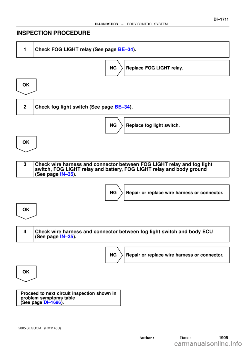
INSPECTION PROCEDURE
1 Check FOG LIGHT relay (See page BE±34).
NG Replace FOG LIGHT relay.
OK
2 Check fog light switch (See page BE±34).
NG Replace fog light switch.
OK
3 Check wire harness and connector between FOG LIGHT relay and fog light
switch, FOG LIGHT relay and battery, FOG LIGHT relay and body ground
(See page IN±35).
NG Repair or replace wire harness or connector.
OK
4 Check wire harness and connector between fog light switch and body ECU
(See page IN±35).
NG Repair or replace wire harness or connector.
OK
Proceed to next circuit inspection shown in
problem symptoms table
(See page DI±1686).
Page 1914 of 4323
DI±1712
± DIAGNOSTICSBODY CONTROL SYSTEM
1906 Author�: Date�:
2005 SEQUOIA (RM1146U)
Daytime running light relay circuit
CIRCUIT DESCRIPTION
Power is supplied to the DIMMER and DRL No. 4 relays when the HEAD relay is turned on.
The HEAD relay turns on by turning the light control switch to the TAIL or HEAD position.
The DIMMER relay turns on by turning the headlight dimmer switch to the LOW, HIGH, or FLASH position.
The body ECU determines the light control switch position and turns on the DRL No. 4 and DIMMER relays.
The DRL No. 4 relay and the daytime running light resistor are parallel circuits. If the light control switch is
OFF, electric current flows to body ground via the resistor instead of driving the DRL No. 4 relay. The head-
lights come on and dim according to the amount of resistance.
DI6M3±11
Page 1915 of 4323
I28771
32
2
1
2Body ECU
2
2 L1
G±W2
2 2
Engine Room R/B No. 2R±W
21
21
21 R±L
A
To Body ECU
(HEAD Relay Circuit)B7
R
2F
B 5
EDMAINHEAD RelayDRLIA117
Battery F10
FL Block J1
J/CW±L
W±L
R±L
R±W
R±WW±B G±W
32
1 W±LW
12 A
A
A
2
22
2
12 3
5
B7 W±B
R W±B
R±LL
L 5
3
21
53
12 12 12G
2C 2D16
4 A2
22
2
2 DIMMER Relay Engine Room R/B No. 2 H5
Headlight
LH
16
17 CH±LP RH
H±ON
DIM DRL No. 4 Relay J4
J/CC H6
Headlight RH
H±LP LH
H±LP RL
H±LP LL
IA118 W±B
4Engine Room R/B No. 2
Engine Room J/B
6
LG±R R±B
J2 J/C
W±L
D1 Daytime Running
Light Resistor
J5
J/C
A
EA
± DIAGNOSTICSBODY CONTROL SYSTEM
DI±1713
1907 Author�: Date�:
2005 SEQUOIA (RM1146U)
WIRING DIAGRAM
Page 1916 of 4323
DI±1714
± DIAGNOSTICSBODY CONTROL SYSTEM
1908 Author�: Date�:
2005 SEQUOIA (RM1146U)
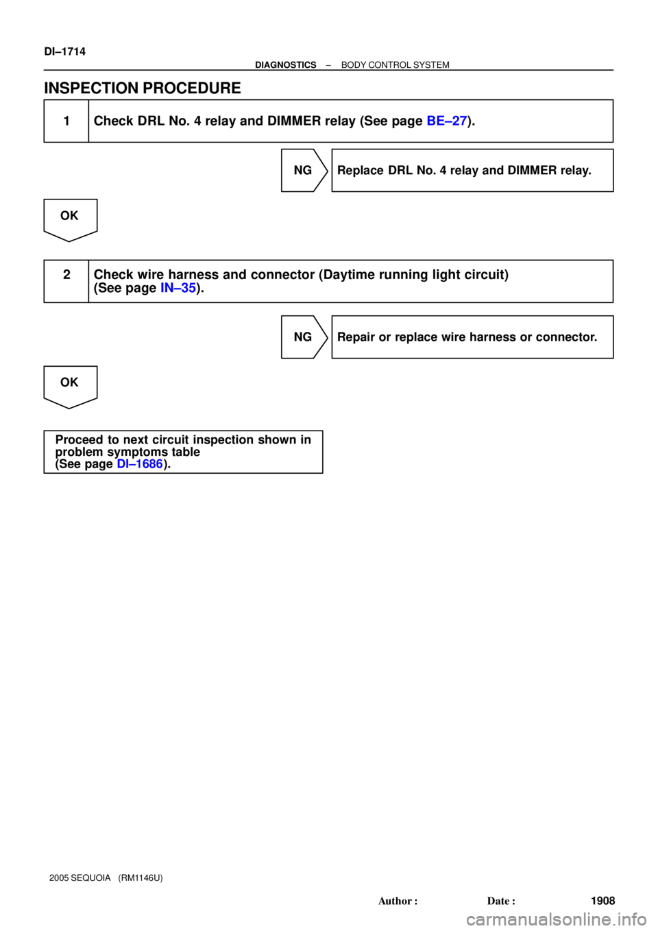
INSPECTION PROCEDURE
1 Check DRL No. 4 relay and DIMMER relay (See page BE±27).
NG Replace DRL No. 4 relay and DIMMER relay.
OK
2 Check wire harness and connector (Daytime running light circuit)
(See page IN±35).
NG Repair or replace wire harness or connector.
OK
Proceed to next circuit inspection shown in
problem symptoms table
(See page DI±1686).
Page 1952 of 4323
I18747
Body ECU
Instrument Panel J/BHEAD
TAIL
A G±Y
G
L±R (*1)B6
137 9
H
TELA
OFF
TAIL
HEAD
AUTO Light
Control
Switch
16
W±B
1B7 9
1F J8
J/C
W±B
A
IE10
14 12
(*1): w/ Automatic Light ControlB6
B6
C8
Combination Switch DI±1750
± DIAGNOSTICSBODY CONTROL SYSTEM
1944 Author�: Date�:
2005 SEQUOIA (RM1146U)
Light control switch circuit
CIRCUIT DESCRIPTION
The body ECU detects the light control switch position and drives the DRL No. 4 and HEAD relays.
If the vehicle is equipped with an automatic light control system, the light control switch includes the AUTO
position.
The body ECU turns the headlights ON and OFF based on the ambient light level outside the vehicle, which
is detected by the automatic light control sensor.
WIRING DIAGRAM
DI1OL±27
Page 1957 of 4323

I28521
1B
1B1
2
7
1B 1F9Y±R
B6
B6 11
8
R±L Instrument Panel J/B
Y±R
W±BHF HU
J8
J/C A
IE16 LOW
HIGH
FLASH Headlight
Dimmer
Switch
W±BC8 Combination Switch
EL HF HU87Body ECU w/ Daytime Running Light:
± DIAGNOSTICSBODY CONTROL SYSTEM
DI±1755
1949 Author�: Date�:
2005 SEQUOIA (RM1146U)
Headlight dimmer switch circuit
CIRCUIT DESCRIPTION
This circuit detects the headlight dimmer switch condition.
w/ daytime running light:
The body ECU detects the headlight dimmer switch position and turns on the DIMMER relay.
The body ECU informs the combination meter of the headlight dimmer switch condition via BEAN.
When the headlight dimmer switch position is HI or FLASH, the HI beam indicator light on the combination
meter comes on.
w/o daytime running light:
When the headlight dimmer switch position is HI or FLASH, the HI beam indicator light on the combination
meter comes on.
When the HI beam headlights come on, current is supplied to the HI beam indicator light on the combination
meter to turn the indicator light on.
WIRING DIAGRAM
DI94U±08
Page 1966 of 4323
I24147
B7
HORN HORN Relay
2
1Body ECU
1
2D18
HR
HORN
B5 B±Y
6 C9
Horn SW
B54 F10
FL Block H8
Horn (low)
1
1 B B8
2H
7
2F5
3W±R W±R19
IA1
26
Battery H7
Horn (high)Engine Room J/B
B DI±1764
± DIAGNOSTICSBODY CONTROL SYSTEM
1958 Author�: Date�:
2005 SEQUOIA (RM1146U)
Horn circuit
CIRCUIT DESCRIPTION
The vehicle horn sounds when the horn switch is pressed. It also sounds as an alarm for the theft deterrent
system when the body ECU detects any alert condition.
WIRING DIAGRAM
DI94T±08
Page 1968 of 4323
DI±1766
± DIAGNOSTICSBODY CONTROL SYSTEM
1960 Author�: Date�:
2005 SEQUOIA (RM1146U)
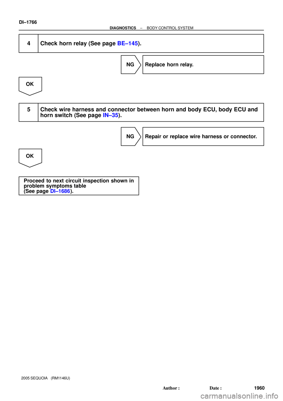
4 Check horn relay (See page BE±145).
NG Replace horn relay.
OK
5 Check wire harness and connector between horn and body ECU, body ECU and
horn switch (See page IN±35).
NG Repair or replace wire harness or connector.
OK
Proceed to next circuit inspection shown in
problem symptoms table
(See page DI±1686).

B7
R
2F
B 5
EDMAINHEAD RelayDRLIA117
Battery F10
FL Block J1
J/CW±L
W±L
R±L
R±W
R")
B6
137 9
H
TELA
OFF
TAIL
HEAD
AUTO Light
Control
Switch
16
W±B
1B7 9
1F J8
J/C
W±B
A
IE10
14 12
(*1): w/ Automatic Light ControlB6
B6")

1
1 B B8
2H
7
2F5
3W±R W±R19
IA1
26
Battery H7
Horn (high)Engine Room J/B
B DI±1764
± DIAG")