Page 3120 of 4323

R04325
SST
R02482
SST
R04326
Front: Rear:
R04327
Matchmarks SA±116
± SUSPENSION AND AXLEREAR DIFFERENTIAL CARRIER
3112 Author�: Date�:
2005 SEQUOIA (RM1146U)
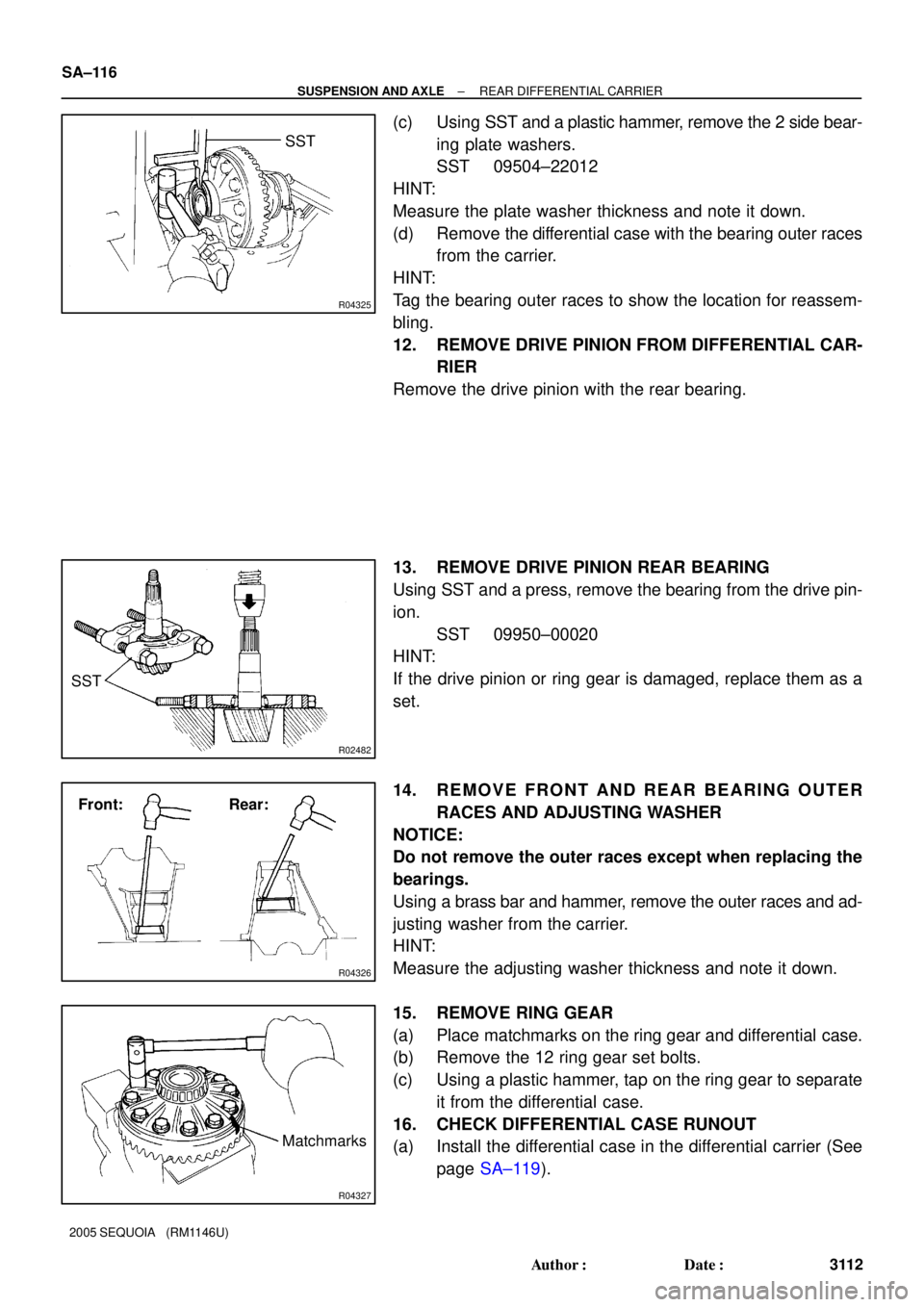
(c) Using SST and a plastic hammer, remove the 2 side bear-
ing plate washers.
SST 09504±22012
HINT:
Measure the plate washer thickness and note it down.
(d) Remove the differential case with the bearing outer races
from the carrier.
HINT:
Tag the bearing outer races to show the location for reassem-
bling.
12. REMOVE DRIVE PINION FROM DIFFERENTIAL CAR-
RIER
Remove the drive pinion with the rear bearing.
13. REMOVE DRIVE PINION REAR BEARING
Using SST and a press, remove the bearing from the drive pin-
ion.
SST 09950±00020
HINT:
If the drive pinion or ring gear is damaged, replace them as a
set.
14. REMOVE FRONT AND REAR BEARING OUTER
RACES AND ADJUSTING WASHER
NOTICE:
Do not remove the outer races except when replacing the
bearings.
Using a brass bar and hammer, remove the outer races and ad-
justing washer from the carrier.
HINT:
Measure the adjusting washer thickness and note it down.
15. REMOVE RING GEAR
(a) Place matchmarks on the ring gear and differential case.
(b) Remove the 12 ring gear set bolts.
(c) Using a plastic hammer, tap on the ring gear to separate
it from the differential case.
16. CHECK DIFFERENTIAL CASE RUNOUT
(a) Install the differential case in the differential carrier (See
page SA±119).
Page 3130 of 4323

R04554
R11163SST SA±126
± SUSPENSION AND AXLEREAR DIFFERENTIAL CARRIER
3122 Author�: Date�:
2005 SEQUOIA (RM1146U)
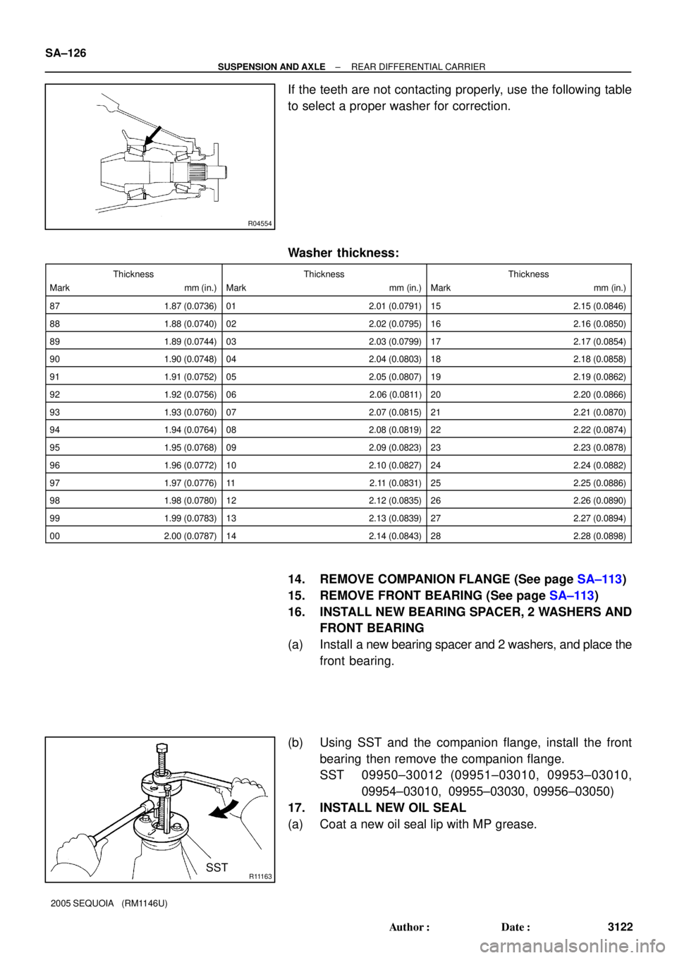
If the teeth are not contacting properly, use the following table
to select a proper washer for correction.
Washer thickness:
Thickness
Mark mm (in.)Thickness
Mark mm (in.)Thickness
Mark mm (in.)
87 1.87 (0.0736)01 2.01 (0.0791)15 2.15 (0.0846)
88 1.88 (0.0740)02 2.02 (0.0795)16 2.16 (0.0850)
89 1.89 (0.0744)03 2.03 (0.0799)17 2.17 (0.0854)
90 1.90 (0.0748)04 2.04 (0.0803)18 2.18 (0.0858)
91 1.91 (0.0752)05 2.05 (0.0807)19 2.19 (0.0862)
92 1.92 (0.0756)06 2.06 (0.0811)20 2.20 (0.0866)
93 1.93 (0.0760)07 2.07 (0.0815)21 2.21 (0.0870)
94 1.94 (0.0764)08 2.08 (0.0819)22 2.22 (0.0874)
95 1.95 (0.0768)09 2.09 (0.0823)23 2.23 (0.0878)
96 1.96 (0.0772)10 2.10 (0.0827)24 2.24 (0.0882)
97 1.97 (0.0776)11 2.11 (0.0831)25 2.25 (0.0886)
98 1.98 (0.0780)12 2.12 (0.0835)26 2.26 (0.0890)
99 1.99 (0.0783)13 2.13 (0.0839)27 2.27 (0.0894)
00 2.00 (0.0787)14 2.14 (0.0843)28 2.28 (0.0898)
14. REMOVE COMPANION FLANGE (See page SA±113)
15. REMOVE FRONT BEARING (See page SA±113)
16. INSTALL NEW BEARING SPACER, 2 WASHERS AND
FRONT BEARING
(a) Install a new bearing spacer and 2 washers, and place the
front bearing.
(b) Using SST and the companion flange, install the front
bearing then remove the companion flange.
SST 09950±30012 (09951±03010, 09953±03010,
09954±03010, 09955±03030, 09956±03050)
17. INSTALL NEW OIL SEAL
(a) Coat a new oil seal lip with MP grease.
Page 3132 of 4323

SA2352
SA2352
SA±128
± SUSPENSION AND AXLEREAR DIFFERENTIAL CARRIER
3124 Author�: Date�:
2005 SEQUOIA (RM1146U)
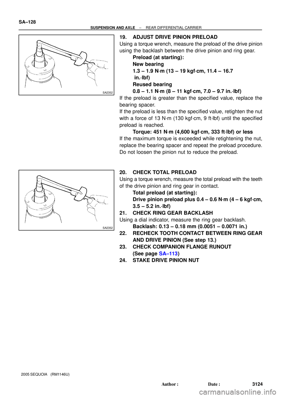
19. ADJUST DRIVE PINION PRELOAD
Using a torque wrench, measure the preload of the drive pinion
using the backlash between the drive pinion and ring gear.
Preload (at starting):
New bearing
1.3 ± 1.9 N´m (13 ± 19 kgf´cm, 11.4 ± 16.7
in.´lbf)
Reused bearing
0.8 ± 1.1 N´m (8 ± 11 kgf´cm, 7.0 ± 9.7 in.´lbf)
If the preload is greater than the specified value, replace the
bearing spacer.
If the preload is less than the specified value, retighten the nut
with a force of 13 N´m (130 kgf´cm, 9 ft´lbf) until the specified
preload is reached.
Torque: 451 N´m (4,600 kgf´cm, 333 ft´lbf) or less
If the maximum torque is exceeded while retightening the nut,
replace the bearing spacer and repeat the preload procedure.
Do not loosen the pinion nut to reduce the preload.
20. CHECK TOTAL PRELOAD
Using a torque wrench, measure the total preload with the teeth
of the drive pinion and ring gear in contact.
Total preload (at starting):
Drive pinion preload plus 0.4 ± 0.6 N´m (4 ± 6 kgf´cm,
3.5 ± 5.2 in.´lbf)
21. CHECK RING GEAR BACKLASH
Using a dial indicator, measure the ring gear backlash.
Backlash: 0.13 ± 0.18 mm (0.0051 ± 0.0071 in.)
22. RECHECK TOOTH CONTACT BETWEEN RING GEAR
AND DRIVE PINION (See step 13.)
23. CHECK COMPANION FLANGE RUNOUT
(See page SA±113)
24. STAKE DRIVE PINION NUT
Page 3133 of 4323
SA15R±13
± SUSPENSION AND AXLEREAR DIFFERENTIAL CARRIER
SA±129
3125 Author�: Date�:
2005 SEQUOIA (RM1146U)
INSTALLATION
1. INSTALL DIFFERENTIAL CARRIER ASSEMBLY
(a) Install a new gasket.
(b) Install the differential carrier assembly with the 10 washers and nuts.
NOTICE:
Be careful not to damage the installation surface.
Torque: 73 N´m (740 kgf´cm, 54 ft´lbf)
2. CONNECT REAR PROPELLER SHAFT
2WD: See page PR±5
4WD: See page PR±9
3. INSTALL REAR AXLE SHAFTS (See page SA±102)
4. FILL DIFFERENTIAL WITH HYPOID GEAR OIL (See page SA±105)
Page 3135 of 4323

SA2CX±01
F17148260 mm (10.236 in.)
F16838Clip
Center Pin
Slotted
Hole
± SUSPENSION AND AXLEREAR PNEUMATIC CYLINDER
SA±131
3127 Author�: Date�:
2005 SEQUOIA (RM1146U)
REMOVAL
NOTICE:
�Do not extend the pneumatic cylinder by itself. If the
cylinder is fully extended, it cannot be reused.
�Do not replenish the pneumatic cylinder by itself with
air.
�Do not remove the pneumatic cylinder with air in it.
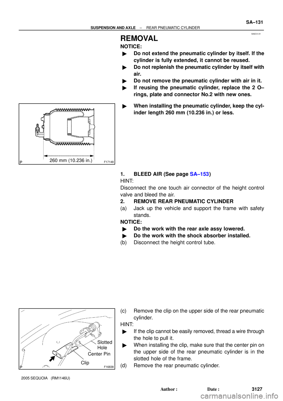
�If reusing the pneumatic cylinder, replace the 2 O±
rings, plate and connector No.2 with new ones.
�When installing the pneumatic cylinder, keep the cyl-
inder length 260 mm (10.236 in.) or less.
1. BLEED AIR (See page SA±153)
HINT:
Disconnect the one touch air connector of the height control
valve and bleed the air.
2. REMOVE REAR PNEUMATIC CYLINDER
(a) Jack up the vehicle and support the frame with safety
stands.
NOTICE:
�Do the work with the rear axle assy lowered.
�Do the work with the shock absorber installed.
(b) Disconnect the height control tube.
(c) Remove the clip on the upper side of the rear pneumatic
cylinder.
HINT:
�If the clip cannot be easily removed, thread a wire through
the hole to pull it.
�When installing the clip, make sure that the center pin on
the upper side of the rear pneumatic cylinder is in the
slotted hole of the frame.
(d) Remove the rear pneumatic cylinder.
Page 3138 of 4323
SA0KM±05
SA±134
± SUSPENSION AND AXLEREAR PNEUMATIC CYLINDER
3130 Author�: Date�:
2005 SEQUOIA (RM1146U)
INSTALLATION
Installation is in the reverse order of removal (See page SA±131).
Page 3146 of 4323
SA176±04
SA±142
± SUSPENSION AND AXLECOIL SPRING AND REAR SHOCK ABSORBER
3138 Author�: Date�:
2005 SEQUOIA (RM1146U)
INSTALLATION
Installation is in the reverse order of removal (See page SA±137).
Page 3149 of 4323
SA179±01
± SUSPENSION AND AXLEREAR LATERAL CONTROL ROD
SA±145
3141 Author�: Date�:
2005 SEQUOIA (RM1146U)
INSTALLATION
Installation is in the reverse order of removal (See page SA±144).