Page 3175 of 4323
SA2CW±01
F16828
F16828
± SUSPENSION AND AXLESUSPENSION CONTROL ECU
SA±171
3167 Author�: Date�:
2005 SEQUOIA (RM1146U)
SUSPENSION CONTROL ECU
REPLACEMENT
1. DISCONNECT CABLE FROM NEGATIVE BATTERY
TERMINAL
2. REMOVE INTEGRATION CONTROL PANEL
(See page BO±89)
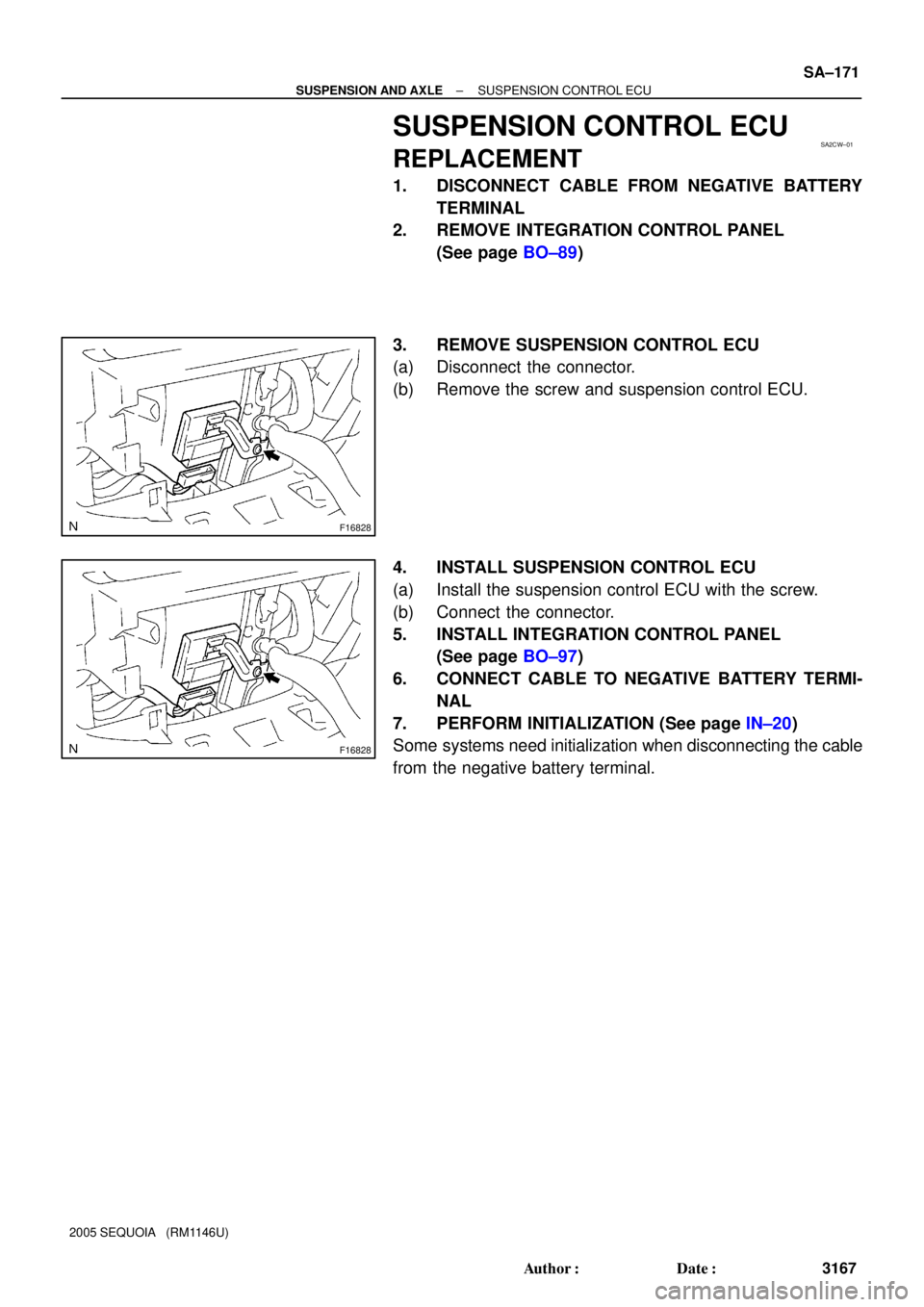
3. REMOVE SUSPENSION CONTROL ECU
(a) Disconnect the connector.
(b) Remove the screw and suspension control ECU.
4. INSTALL SUSPENSION CONTROL ECU
(a) Install the suspension control ECU with the screw.
(b) Connect the connector.
5. INSTALL INTEGRATION CONTROL PANEL
(See page BO±97)
6. CONNECT CABLE TO NEGATIVE BATTERY TERMI-
NAL
7. PERFORM INITIALIZATION (See page IN±20)
Some systems need initialization when disconnecting the cable
from the negative battery terminal.
Page 3177 of 4323

TROUBLESHOOTING
PROBLEM SYMPTOMS TABLE
Use the table below to help you find the cause of the problem. The numbers")
BR08P±07
BR±2
± BRAKETROUBLESHOOTING
3169 Author�: Date�:
2005 SEQUOIA (RM1146U)
TROUBLESHOOTING
PROBLEM SYMPTOMS TABLE
Use the table below to help you find the cause of the problem. The numbers indicate the priority of the likely
cause of the problem. Check each part in order. If necessary, replace these parts.
SymptomSuspect AreaSee page
Low pedal or spongy pedal
1. Fluid leaks for brake system
2. Air in brake system
3. Piston seals (Worn or damaged)
4. Master cylinder (Faulty)DI±1059
BR±4
BR±27
BR±36
BR±15
Brake drags
1. Brake pedal free play (Minimum)
2. Parking brake pedal travel (Out of adjustment)
3. Parking brake wire (Sticking)
4. Parking brake (Shoe clearance out of adjustment)
5. Pad (Cracked or distorted)
6. Piston (Stuck)
7. Piston (Frozen)
8. Tension or return spring (Faulty)
9. Vacuum leaks for booster system
10.Master cylinder (Faulty)BR±6
BR±9
±
BR±42
BR±24
BR±33
BR±27
BR±36
BR±27
BR±36
BR±42
BR±21
BR±15
Brake pulls
1. Piston (Stuck)
2. Pad (Cracked or distorted)
3. Piston (Frozen)
4. Disc (Scored)
5. Vacuum leaks for booster system
6. Master cylinder (Faulty)BR±27
BR±36
BR±24
BR±33
BR±27
BR±36
BR±30
BR±39
BR±21
BR±15
Page 3180 of 4323
± BRAKEBRAKE FLUID
BR±5
3172 Author�: Date�:
2005 SEQUOIA (RM1146U)
(e) Repeat the procedure on the previous page to bleed the
air out of brake line for each wheel.
4. CHECK FLUID LEVEL IN RESERVOIR
Check the fluid level and add fluid if necessary.
Fluid: SAE J1703 or FMVSS No. 116 DOT3
Page 3181 of 4323

BRAKE PEDAL
ON±VEHICLE INSPECTION
1. CHECK PEDAL HEIGHT
Pedal hei")
F07754
Pedal Height Push Rod
BR107±04
R00085
Pedal Free Play BR±6
± BRAKEBRAKE PEDAL
3173 Author�: Date�:
2005 SEQUOIA (RM1146U)
BRAKE PEDAL
ON±VEHICLE INSPECTION
1. CHECK PEDAL HEIGHT
Pedal height from dash panel:
151.1 ± 165.1 mm (5.949 ± 6.500 in.)
NOTICE:
Do not adjust the pedal height. Doing so by changing the
push rod length of the brake booster will structurally
change the pedal ratio.
If the pedal height is incorrect, check that there is no damage
in brake pedal, brake pedal lever, brake pedal bracket and dash
panel.
�Even if there is damage, there is no problem if the
reserve distance is within the standard value.
�If necessary, replace them.
2. IF NECESSARY, ADJUST STOP LIGHT SWITCH
(a) Remove the front door scuff plate, cowl side trim, side
panel, lower finish panel and No. 2 heater to register duct
(See page BO±89).
(b) Loosen the stop light switch lock nut.
(c) Push the brake pedal in 5 ± 15 mm (0.20 ± 0.59 in.), turn
the stop light switch to lock the nut in the position where
the stop light goes off.
(d) Push the brake pedal in 5 ±15 mm (0.20 ± 0.59 in.), check
that the stop light lights up.
(e) Install the No. 2 heater to register duct, lower finish panel,
side panel, cowl side trim and front door scuff plate (See
page BO±89).
3. CHECK PEDAL FREE PLAY
(a) Stop the engine and depress the brake pedal several
times until there is no more vacuum left in the booster.
(b) Push in the pedal by hand until the second point of resis-
tance begins to be felt, then measure the distance as
shown in the illustration.
Pedal free play: 1 ± 6 mm (0.04 ± 0.24 in.)
HINT:
The free play to the first point of resistance is due to the play
between the clevis and pin. It is 1 ± 3 mm (0.04 ± 0.12 in.) at the
pedal.
If incorrect, check the stop light switch clearance. If the clear-
ance is OK, then troubleshoot the brake system.
Stop light switch clearance:
0.5 ± 2.4 mm (0.020 ± 0.095 in.)
Page 3184 of 4323

PARKING BRAKE PEDAL
ON±VEHICLE INSPECTION
1. CHECK PARKING BRAKE PEDAL T")
F13902
BR109±04
F13896
Adjusting
Nut
Lock Nut
± BRAKEPARKING BRAKE PEDAL
BR±9
3176 Author�: Date�:
2005 SEQUOIA (RM1146U)
PARKING BRAKE PEDAL
ON±VEHICLE INSPECTION
1. CHECK PARKING BRAKE PEDAL TRAVEL
Depress the parking brake pedal all the way and count the num-
ber of clicks.
Parking brake pedal travel at 300 N (31 kgf, 67 lbf):
6 ± 9 clicks
If incorrect, adjust the parking brake.
2. IF NECESSARY, ADJUST PARKING BRAKE PEDAL
TRAVEL
HINT:
Before adjusting the parking brake, make sure that the rear
brake shoe clearance has been adjusted. For shoe clearance
adjustment, see step 1 on page BR±47.
(a) Remove the front door scuff plate, cowl side trim board,
side panel, lower finish panel and No. 2 heater to register
duct (See page BO±89).
(b) Loosen the lock nut and turn the adjusting nut until the
pedal travel is correct.
(c) Tighten the lock nut.
Torque: 5.4 N´m (55 kgf´cm, 48 in.´lbf)
(d) Install the No. 2 heater to register duct, lower finish panel,
side panel, cowl side trim and front door scuff plate.
Page 3186 of 4323
BR10B±04
± BRAKEPARKING BRAKE PEDAL
BR±11
3178 Author�: Date�:
2005 SEQUOIA (RM1146U)
REMOVAL
1. REMOVE FRONT DOOR SCUFF PLATE, COWL SIDE TRIM BOARD, SIDE PANEL, LOWER FIN-
ISH PANEL AND NO. 2 HEATER TO REGISTER DUCT (See page BO±89)
2. REMOVE PARKING BRAKE PEDAL ASSEMBLY
(a) Disconnect the parking brake switch connector.
(b) Remove the lock nut and adjusting nut from the parking brake wire.
Torque: 5.4 N´m (55 kgf´cm, 48 in.´lbf)
(c) Remove the clip and disconnect the parking brake wire from the parking brake pedal assembly.
(d) Remove the 4 bolts and parking brake pedal assembly.
Torque: 13 N´m (130 kgf´cm, 9 ft´lbf)
Page 3188 of 4323
BR1NC±02
± BRAKEPARKING BRAKE PEDAL
BR±13
3180 Author�: Date�:
2005 SEQUOIA (RM1146U)
REASSEMBLY
Reassembly is in the reverse order of disassembly (See page BR±12).
NOTICE:
Apply lithium soap base glycol grease to the parts indicated by the arrows (See page BR±10).
Page 3189 of 4323
BR10C±03
BR±14
± BRAKEPARKING BRAKE PEDAL
3181 Author�: Date�:
2005 SEQUOIA (RM1146U)
INSTALLATION
Installation is in the reverse order of removal (See page BR±11).
HINT:
After the installation, check and adjust parking brake pedal travel (See page BR±9).