Page 3241 of 4323

F13254
INOUTAttachment
Pressure Feed Tube
SST
Z15498
Oil
Reservoir
PS Vane
Pump PS Gear
SST Closed
Z15499
Oil
Reservoir
PS Vane
Pump PS Gear
SST Open SR±6
± STEERINGPOWER STEERING FLUID
3233 Author�: Date�:
2005 SEQUOIA (RM1146U)
2. CHECK STEERING FLUID PRESSURE
(a) Remove the air cleaner assembly with the air cleaner
hose connected (See page SR±26).
(b) Disconnect the pressure feed tube from the PS vane
pump (See page SR±26).
(c) Connect SST, as shown in the illustration.
SST 09640±10010 (09641±01010, 09641±01030,
09641±01060)
NOTICE:
Check that the valve of the SST is in the open position.
(d) Bleed the power steering system (See page SR±4).
(e) Start the engine and run at idle.
(f) Turn the steering wheel from the lock position to the other
side of lock position several times to boost fluid tempera-
ture.
Fluid temperature: 80 °C (176 °F)
(g) With the engine idling, close the valve of the SST and ob-
serve the reading on the SST.
Minimum fluid pressure:
8,336 kPa (85 kgf/cm
2, 1,209 psi)
NOTICE:
�Do not keep the valve closed for more than 10 se-
conds.
�Do not let the fluid temperature become too high.
(h) With the engine idling, open the valve fully.
(i) Measure the fluid pressure at engine speeds of 1,000 rpm
and 3,000 rpm.
Difference in fluid pressure:
490 kPa (5 kgf/cm
2, 71 psi) or less
NOTICE:
Do not turn the steering wheel.
Page 3242 of 4323
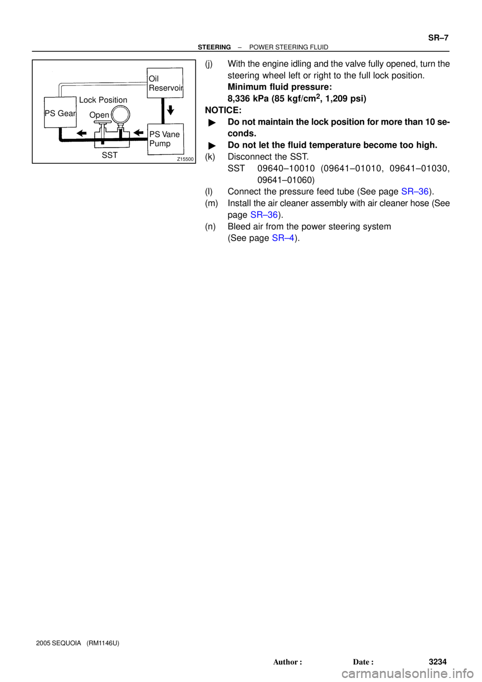
Z15500
Oil
Reservoir
PS Vane
Pump PS Gear
SST Open Lock Position
± STEERINGPOWER STEERING FLUID
SR±7
3234 Author�: Date�:
2005 SEQUOIA (RM1146U)
(j) With the engine idling and the valve fully opened, turn the
steering wheel left or right to the full lock position.
Minimum fluid pressure:
8,336 kPa (85 kgf/cm
2, 1,209 psi)
NOTICE:
�Do not maintain the lock position for more than 10 se-
conds.
�Do not let the fluid temperature become too high.
(k) Disconnect the SST.
SST 09640±10010 (09641±01010, 09641±01030,
09641±01060)
(l) Connect the pressure feed tube (See page SR±36).
(m) Install the air cleaner assembly with air cleaner hose (See
page SR±36).
(n) Bleed air from the power steering system
(See page SR±4).
Page 3244 of 4323
R07653
SR01Y±11
R09732
± STEERINGSTEERING WHEEL
SR±9
3236 Author�: Date�:
2005 SEQUOIA (RM1146U)
STEERING WHEEL
INSPECTION
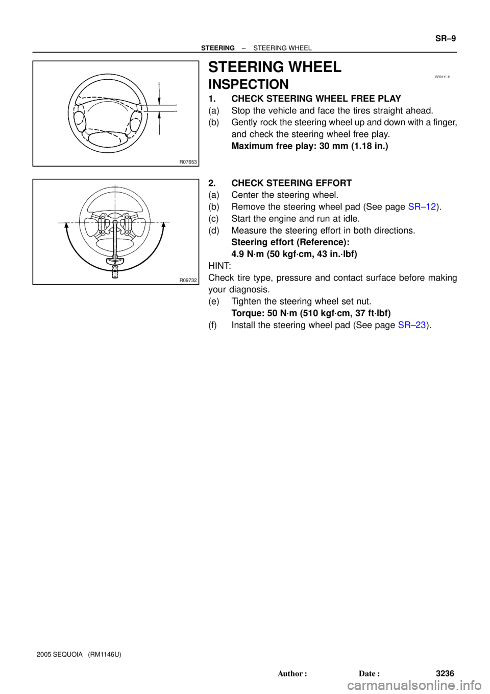
1. CHECK STEERING WHEEL FREE PLAY
(a) Stop the vehicle and face the tires straight ahead.
(b) Gently rock the steering wheel up and down with a finger,
and check the steering wheel free play.
Maximum free play: 30 mm (1.18 in.)
2. CHECK STEERING EFFORT
(a) Center the steering wheel.
(b) Remove the steering wheel pad (See page SR±12).
(c) Start the engine and run at idle.
(d) Measure the steering effort in both directions.
Steering effort (Reference):
4.9 N´m (50 kgf´cm, 43 in.´lbf)
HINT:
Check tire type, pressure and contact surface before making
your diagnosis.
(e) Tighten the steering wheel set nut.
Torque: 50 N´m (510 kgf´cm, 37 ft´lbf)
(f) Install the steering wheel pad (See page SR±23).
Page 3250 of 4323

5. REMOVE COMBINATION SWITCH WITH SPIRAL
CABLE
(a) Disconnect the 4 connectors.")
F17896
A
BMatchmarks
F13260
F06703
± STEERINGTILT STEERING COLUMN
SR±15
3242 Author�: Date�:
2005 SEQUOIA (RM1146U)
5. REMOVE COMBINATION SWITCH WITH SPIRAL
CABLE
(a) Disconnect the 4 connectors.
(b) Disconnect the airbag connector.
(c) Remove the 3 screws and combination switch.
6. REMOVE SPIRAL CABLE (See page BE±26)
NOTICE:
Do not disassemble the cable or apply oil to it.
7. REMOVE COWL SIDE TRIM AND FRONT DOOR
SCUFF PLATE
8. REMOVE LOWER LH FINISH PANEL
(a) Remove the 2 screws and disconnect the hood lock re-
lease lever from the panel.
(b) Remove the 4 panel set bolts and lower LH finish panel.
9. REMOVE NO. 2 HEATER TO REGISTER DUCT
10. REMOVE BRAKE PEDAL RETURN SPRING
11. REMOVE SLIDING YOKE
(a) Put matchmarks on the sliding yoke and No. 2 intermedi-
ate shaft assembly.
(b) Remove the ºAº bolt.
(c) Remove the ºBº bolt.
(d) Slide the sliding yoke and remove it.
12. REMOVE COLUMN HOLE COVER NO. 2
Remove the 3 bolts and column hole cover No. 2.
13. DISCONNECT TRANSMISSION CONTROL CABLE
ASSEMBLY
Disconnect the cable assembly from the column shift lever as-
sembly.
14. REMOVE STEERING COLUMN ASSEMBLY WITH
NO. 2 UNIVERSAL JOINT ASSEMBLY
(a) Disconnect the connectors.
(b) Remove the 4 steering column set nuts.
(c) Pull out the steering column assembly with the No. 2 uni-
versal joint assembly connected.
Page 3252 of 4323
SR0V1±06
F13611
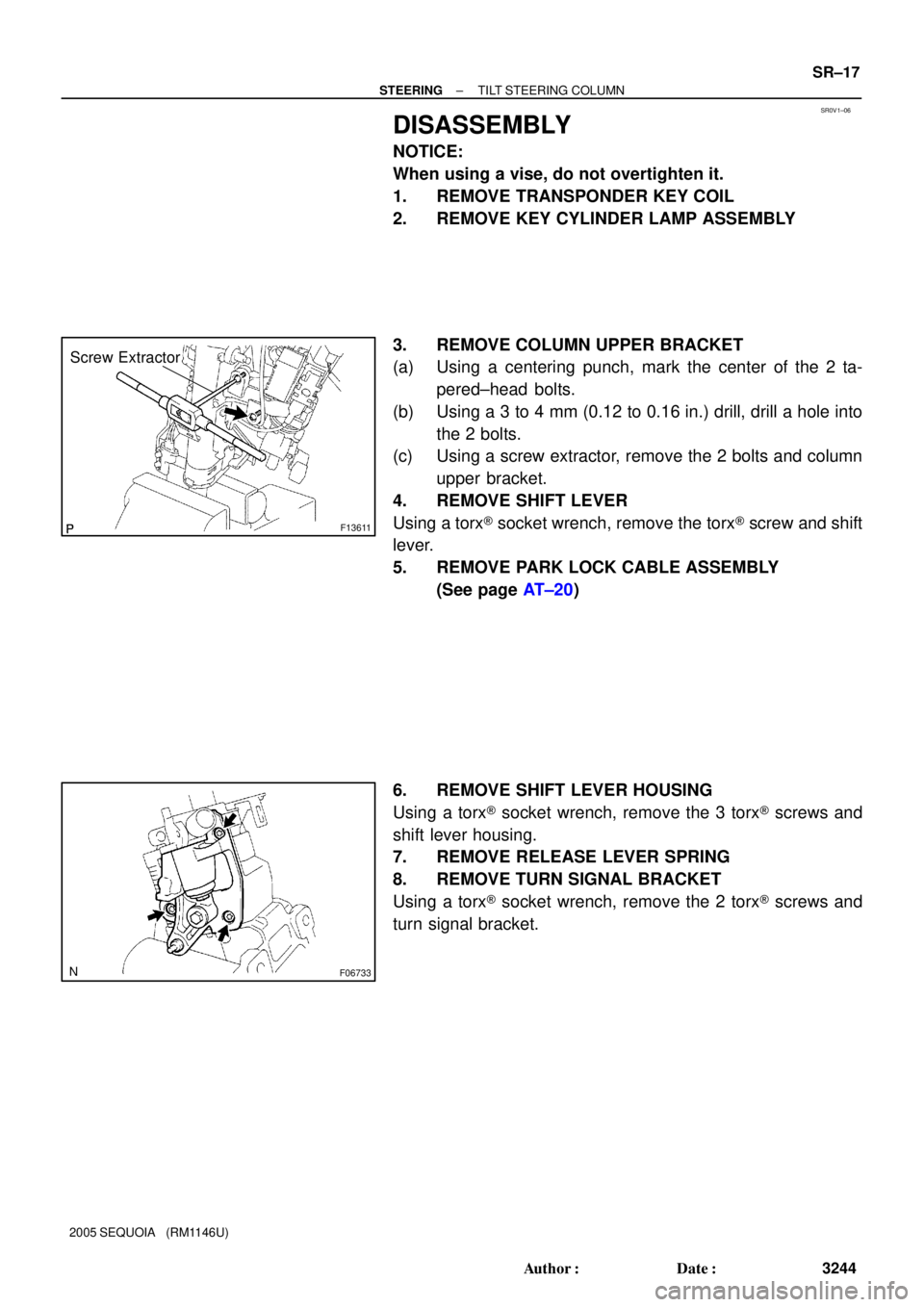
Screw Extractor
F06733
± STEERINGTILT STEERING COLUMN
SR±17
3244 Author�: Date�:
2005 SEQUOIA (RM1146U)
DISASSEMBLY
NOTICE:
When using a vise, do not overtighten it.
1. REMOVE TRANSPONDER KEY COIL
2. REMOVE KEY CYLINDER LAMP ASSEMBLY
3. REMOVE COLUMN UPPER BRACKET
(a) Using a centering punch, mark the center of the 2 ta-
pered±head bolts.
(b) Using a 3 to 4 mm (0.12 to 0.16 in.) drill, drill a hole into
the 2 bolts.
(c) Using a screw extractor, remove the 2 bolts and column
upper bracket.
4. REMOVE SHIFT LEVER
Using a torx® socket wrench, remove the torx® screw and shift
lever.
5. REMOVE PARK LOCK CABLE ASSEMBLY
(See page AT±20)
6. REMOVE SHIFT LEVER HOUSING
Using a torx® socket wrench, remove the 3 torx® screws and
shift lever housing.
7. REMOVE RELEASE LEVER SPRING
8. REMOVE TURN SIGNAL BRACKET
Using a torx® socket wrench, remove the 2 torx® screws and
turn signal bracket.
Page 3254 of 4323

INSPECTION
1. INSPECT STEERING LOCK OPERATION
Check that the steering lock mechanism")
SR0V2±05
F13613
F13618
R11908
± STEERINGTILT STEERING COLUMN
SR±19
3246 Author�: Date�:
2005 SEQUOIA (RM1146U)
INSPECTION
1. INSPECT STEERING LOCK OPERATION
Check that the steering lock mechanism operates properly.
2. IF NECESSARY, REPLACE KEY CYLINDER
(a) Turn the ignition key to the ACC position.
(b) Push down the stop pin with a screwdriver, and pull out
the cylinder.
(c) Install a new cylinder.
HINT:
Make sure that the key is in the ACC position.
3. INSPECT IGNITION SWITCH (See page BE±24)
4. IF NECESSARY, REPLACE IGNITION SWITCH
(a) Remove the 2 screws and ignition switch.
(b) Install a new ignition switch with the 2 screws.
5. INSPECT KEY UNLOCK WARNING SWITCH
(See page BE±24)
6. IF NECESSARY, REPLACE KEY UNLOCK WARNING
SWITCH
(a) Slide out the key unlock warning switch.
(b) Install a new key unlock warning switch.
7. INSPECT TRANSPONDER KEY COIL
(See page BE±143)
8. IF NECESSARY, REPLACE TRANSPONDER KEY
COIL
9. IF NECESSARY, REPLACE TRANSPONDER KEY AM-
PLIFIER
(a) Remove the screw and transponder key amplifier.
(b) Install a new transponder key amplifier with the screw.
10. INSPECT BEARING
(a) Check that the bearing rotates smoothly without abnor-
mal noise.
If it does not rotate smoothly or abnormal noise occurs, replace
the column housing.
(b) Coat the bearing with molybdenum disulfide lithium base
grease.
Page 3256 of 4323

REASSEMBLY
NOTICE:
When using a vise, do not overtighten it")
SR0V3±05
R12807
Washer
Retaining RingSST
F06735
F06736
± STEERINGTILT STEERING COLUMN
SR±21
3248 Author�: Date�:
2005 SEQUOIA (RM1146U)
REASSEMBLY
NOTICE:
When using a vise, do not overtighten it.
1. COAT PARTS INDICATED BY ARROWS WITH MOLYB-
DENUM DISULFIDE LITHIUM BASE GREASE (See
page SR±12)
2. INSTALL TILT LEVER
Install the tilt lever with a new tilt lever lock shaft.
Torque: 9.0 N´m (90 kgf´cm, 78 in.´lbf)
3. INSTALL MAIN SHAFT ASSEMBLY
(a) Install the inner race, upper bearing inner race seat, com-
pression spring and spring retainer.
(b) Install a new No. 2 steering column ring to the main shaft
assembly.
(c) Install the washer of SST on the main shaft assembly.
SST 09612±07010
(d) Set SST on the main shaft assembly, as shown in the il-
lustration.
SST 09612±07010
(e) Using SST, push down the retaining ring until it fits into the
shaft groove and install the main shaft assembly.
NOTICE:
Do not bend the universal joint of the shaft assembly more
than 15°.
HINT:
Hold the main shaft assembly with your hand to prevent rota-
tion.
4. INSTALL MAIN SHAFT STOPPER
5. INSTALL 2 NEW TILT NO. 1 STOPPERS
6. INSTALL STEERING COLUMN HOUSING WITH MAIN
SHAFT ASSEMBLY
(a) Install the steering column housing with the main shaft as-
sembly into the column tube assembly.
(b) Install the tilt spring and spring guide.
(c) Hold the steering column housing and steering column
housing support in a vise.
(d) Temporarily install 2 new pivot pins.
(e) Using a punch and a hammer, tap in the pivot pin.
(f) Using a pin punch and a hammer, stake at 3 places evenly
around the hole as shown in the illustration.
Page 3257 of 4323

7. INSTALL TURN SIGNAL BRACKET
Using a torx® socket wrench, install the turn signal bracket with
2 n")
F06737
F13612
SR±22
± STEERINGTILT STEERING COLUMN
3249 Author�: Date�:
2005 SEQUOIA (RM1146U)
7. INSTALL TURN SIGNAL BRACKET
Using a torx® socket wrench, install the turn signal bracket with
2 new torx® screws.
Torque: 7.5 N´m (75 kgf´cm, 65 in.´lbf)
HINT:
Make sure that the protrusion on the steering column housing
is fitted into the hole of the turn signal bracket.
8. INSTALL RELEASE LEVER SPRING
9. INSTALL SHIFT LEVER HOUSING
Using a torx® socket wrench, install the shift lever housing with
3 new torx® screws.
Torque: 12 N´m (120 kgf´cm, 9 ft´lbf)
10. INSTALL PARK LOCK CABLE ASSEMBLY (See page
AT±21)
11. INSTALL SHIFT LEVER
Using a torx® socket wrench, install the shift lever with a new
torx® screw.
Torque: 18 N´m (180 kgf´cm, 13 ft´lbf)
12. INSTALL COLUMN UPPER BRACKET
(a) Install the column upper bracket with 2 new tapered±
head bolts.
HINT:
Insert the bracket pin into the column tube hole.
(b) Tighten the tapered±head bolts until the bolt heads break
off.
13. INSTALL KEY CYLINDER LAMP ASSEMBLY
14. INSTALL TRANSPONDER KEY COIL