Page 3209 of 4323

REPLACEMENT
1. REMOVE REAR WHEEL
2. INSPECT PAD LINING THICKNESS
Check the pad thickness through the")
BR0TB±07
F13313
F13314
BR±34
± BRAKEREAR BRAKE PAD
3201 Author�: Date�:
2005 SEQUOIA (RM1146U)
REPLACEMENT
1. REMOVE REAR WHEEL
2. INSPECT PAD LINING THICKNESS
Check the pad thickness through the caliper inspection hole
and replace pads if not within the specification.
Minimum thickness: 1.0 mm (0.039 in.)
3. REMOVE BRAKE CALIPER
(a) Remove the 2 sliding pins.
(b) Remove the caliper and suspend it so the hose is not
stretched.
HINT:
Do not disconnect the flexible hose.
4. REMOVE 2 PADS WITH 2 ANTI±SQUEAL SHIMS
5. REMOVE 4 PAD SUPPORT PLATES
NOTICE:
The pad support plates can be used again provided that
they have sufficient rebound, no deformation, cracks or
wear, and have had all rust, dirt and foreign particles
cleaned off.
6. CHECK DISC THICKNESS AND RUNOUT
(See page BR±39)
7. INSTALL PAD SUPPORT PLATES
8. INSTALL NEW PADS
NOTICE:
When replacing worn pads, the anti±squeal shims must be
replaced together with the pads.
(a) Install the pad wear indicator plate on new inner pad.
(b) Install the anti±squeal shim on each pad.
(c) Install the inner pad with the pad wear indicator plate fac-
ing downward.
(d) Install outer pad.
NOTICE:
There should be no oil or grease adhering to the friction
surfaces of the pads or the disc.
9. INSTALL CALIPER
(a) Draw out a small amount of brake fluid from the reservoir.
Page 3214 of 4323

INSPECTION
1. MEASURE PAD LINING THICKNESS
Using a ruler, measure the pad lining thicknes")
BR0JU±14
F13320
F13321
F13322
± BRAKEREAR BRAKE CALIPER
BR±39
3206 Author�: Date�:
2005 SEQUOIA (RM1146U)
INSPECTION
1. MEASURE PAD LINING THICKNESS
Using a ruler, measure the pad lining thickness.
Standard thickness: 10.0 mm (0.39 in.)
Minimum thickness: 1.0 mm (0.039 in.)
Replace the pad if the pad's thickness is at the minimum or if
it shows signs of uneven wear.
2. MEASURE DISC THICKNESS
(a) Temporarily fasten the disc with the 3 hub nuts.
(b) Using a micrometer, measure the disc thickness.
Standard thickness: 18.0 mm (0.709 in.)
Minimum thickness: 16.0 mm (0.611 in.)
Replace the disc if the thickness of the disc is at the minimum
thickness or less. Replace the disc or grind it on a lathe if it is
scored or is worn unevenly.
3. MEASURE DISC RUNOUT
Using a dial indicator, measure the disc runout at a position 10
mm (0.39 in.) from the outside edge.
Maximum disc runout: 0.1 mm (0.0039 in.)
If the disc's runout is at the maximum value or greater, check the
bearing play is in the axial direction and check the axle hub run-
out (See page SA±95). If the bearing play and axle hub runout
are not abnormal, adjust the disc runout or grind it on an ºOn±
Carº brake lathe.
4. IF NECESSARY, ADJUST DISC RUNOUT
(a) Remove the 2 bolts and torque plate from the backing
plate.
(b) Remove the hub nuts and the disc. Reinstall the disc ro-
tating 1/6 of a turn from its original position on the hub.
Install and torque the hub nuts.
Torque: 110 N´m (1,122 kgf´cm, 81 ft´lbf)
Remeasure the disc runout. Make a note of the runout
and the disc's position on the hub.
(c) Repeat (b) until the disc has been installed on the 4 re-
maining hub positions.
(d) If the minimum runout recorded in (b) and (c) is less than
0.1 mm (0.0039 in.), install the disc in that position.
(e) If the minimum runout recorded in (b) and (c) is greater
than 0.1 mm (0.0039 in.), replace the disc and repeat step
3.
(f) Install the torque plate and tighten the 2 bolts.
Torque: 105 N´m (1,070 kgf´cm, 77 ft´lbf)
Page 3215 of 4323
BR0JV±09
BR±40
± BRAKEREAR BRAKE CALIPER
3207 Author�: Date�:
2005 SEQUOIA (RM1146U)
REASSEMBLY
Reassembly is in the reverse order of disassembly (See page BR±38).
HINT:
Apply lithium soap base glycol grease to the parts indicated by the arrows (See page BR±36).
Page 3216 of 4323
BR0JW±10
± BRAKEREAR BRAKE CALIPER
BR±41
3208 Author�: Date�:
2005 SEQUOIA (RM1146U)
INSTALLATION
Installation is in the reverse order of removal (See page BR±37).
HINT:
�After installation, fill the brake reservoir with brake fluid and bleed brake system (See page BR±4).
�Check for leaks.
Page 3218 of 4323

DISASSEMBLY
1. REMOVE REAR WHEEL
Torque: 110 N´m (1,122 kgf´cm, 81 ft´lbf)
2. REMOVE REAR D")
BR1NF±02
F13327
F13323
F13324
± BRAKEPARKING BRAKE
BR±43
3210 Author�: Date�:
2005 SEQUOIA (RM1146U)
DISASSEMBLY
1. REMOVE REAR WHEEL
Torque: 110 N´m (1,122 kgf´cm, 81 ft´lbf)
2. REMOVE REAR DISC BRAKE ASSEMBLY
(a) Remove the 2 mounting bolts and remove the disc brake
assembly.
Torque: 105 N´m (1,070 kgf´cm, 77 ft´lbf)
(b) Suspend the disc brake securely and so the hose is not
stretched.
3. REMOVE DISC
(a) Release the parking brake lever.
(b) Place matchmarks on the disc and rear axle hub.
(c) Remove the disc.
HINT:
�If the disc cannot be removed easily, turn the shoe adjust-
er until the wheel turns freely.
�If there are no matchmarks, temporarily install the disc,
then measure the disc runout and install the disc in posi-
tion (See page BR±39).
4. REMOVE SHOE RETURN SPRINGS
Using needle±nose pliers, remove the 2 shoe return springs.
5. REMOVE SHOE STRUT WITH SPRING
HINT:
At the time of reassembly, install the strut with the spring facing
forward.
6. REMOVE SHOE ADJUSTER
Slide the front shoe toward outside, remove the shoe adjuster.
7. REMOVE FRONT SHOE
(a) Using a needle±nose pliers, disconnect the anchor spring
and tension spring from the front shoe.
(b) Remove the anchor spring and tension spring.
Page 3222 of 4323
BR0K0±11
F13903
Expand
± BRAKEPARKING BRAKE
BR±47
3214 Author�: Date�:
2005 SEQUOIA (RM1146U)
REASSEMBLY
Reassembly is in the reverse order of disassembly
(See page BR±43).
HINT:
Apply high temperature grease to the parts indicated by the ar-
rows (See page BR±42).
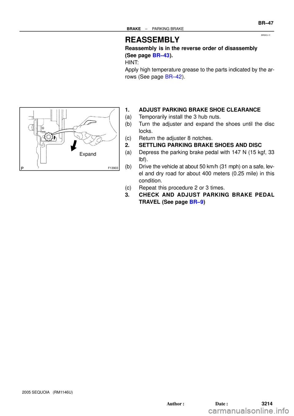
1. ADJUST PARKING BRAKE SHOE CLEARANCE
(a) Temporarily install the 3 hub nuts.
(b) Turn the adjuster and expand the shoes until the disc
locks.
(c) Return the adjuster 8 notches.
2. SETTLING PARKING BRAKE SHOES AND DISC
(a) Depress the parking brake pedal with 147 N (15 kgf, 33
lbf).
(b) Drive the vehicle at about 50 km/h (31 mph) on a safe, lev-
el and dry road for about 400 meters (0.25 mile) in this
condition.
(c) Repeat this procedure 2 or 3 times.
3. CHECK AND ADJUST PARKING BRAKE PEDAL
TRAVEL (See page BR±9)
Page 3224 of 4323
± BRAKEABS & VSC ACTUATOR
BR±49
3216 Author�: Date�:
2005 SEQUOIA (RM1146U)
5. CLEAR DTC (See page DI±911)
Page 3226 of 4323
BR1NI±03
F16315
Release Bar
F16316
± BRAKEABS & VSC ACTUATOR
BR±51
3218 Author�: Date�:
2005 SEQUOIA (RM1146U)
REMOVAL
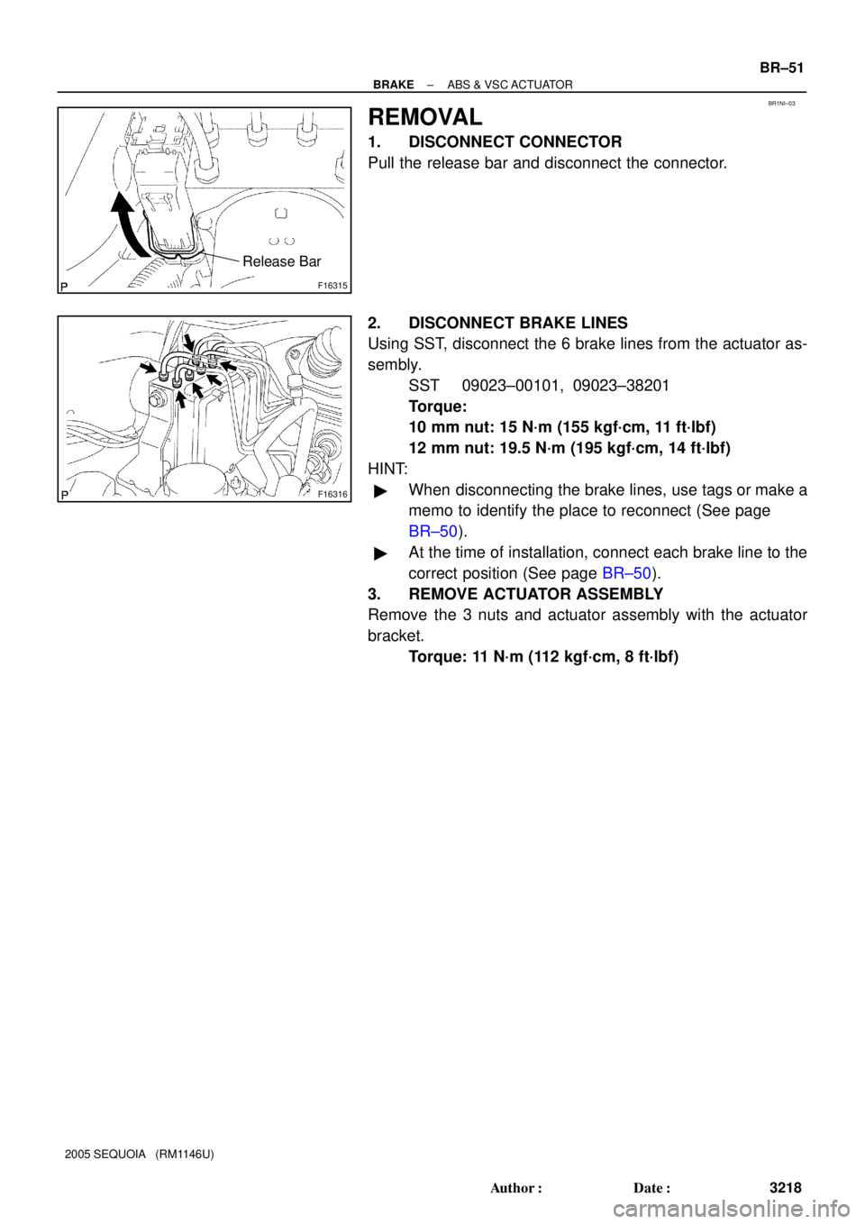
1. DISCONNECT CONNECTOR
Pull the release bar and disconnect the connector.
2. DISCONNECT BRAKE LINES
Using SST, disconnect the 6 brake lines from the actuator as-
sembly.
SST 09023±00101, 09023±38201
Torque:
10 mm nut: 15 N´m (155 kgf´cm, 11 ft´lbf)
12 mm nut: 19.5 N´m (195 kgf´cm, 14 ft´lbf)
HINT:
�When disconnecting the brake lines, use tags or make a
memo to identify the place to reconnect (See page
BR±50).
�At the time of installation, connect each brake line to the
correct position (See page BR±50).
3. REMOVE ACTUATOR ASSEMBLY
Remove the 3 nuts and actuator assembly with the actuator
bracket.
Torque: 11 N´m (112 kgf´cm, 8 ft´lbf)