Page 3313 of 4323
H24695
RS117±01
H20642
H23201
Horn Button Contact Plate
H24696
RS±22
± SUPPLEMENTAL RESTRAINT SYSTEMSTEERING WHEEL PAD AND SPIRAL CABLE
3305 Author�: Date�:
2005 SEQUOIA (RM1146U)
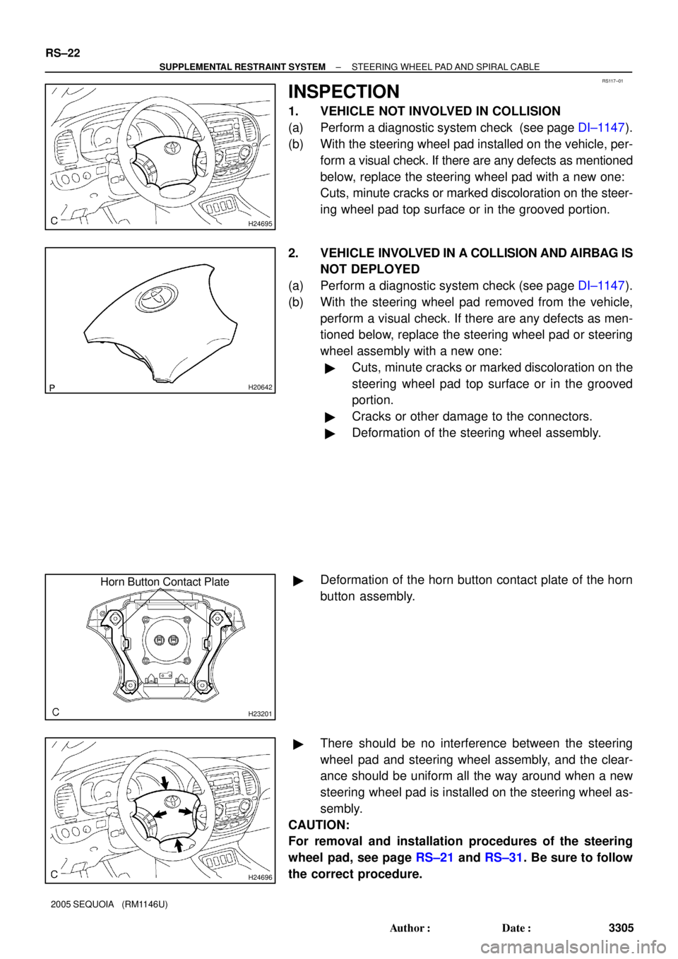
INSPECTION
1. VEHICLE NOT INVOLVED IN COLLISION
(a) Perform a diagnostic system check (see page DI±1147).
(b) With the steering wheel pad installed on the vehicle, per-
form a visual check. If there are any defects as mentioned
below, replace the steering wheel pad with a new one:
Cuts, minute cracks or marked discoloration on the steer-
ing wheel pad top surface or in the grooved portion.
2. VEHICLE INVOLVED IN A COLLISION AND AIRBAG IS
NOT DEPLOYED
(a) Perform a diagnostic system check (see page DI±1147).
(b) With the steering wheel pad removed from the vehicle,
perform a visual check. If there are any defects as men-
tioned below, replace the steering wheel pad or steering
wheel assembly with a new one:
�Cuts, minute cracks or marked discoloration on the
steering wheel pad top surface or in the grooved
portion.
�Cracks or other damage to the connectors.
�Deformation of the steering wheel assembly.
�Deformation of the horn button contact plate of the horn
button assembly.
�There should be no interference between the steering
wheel pad and steering wheel assembly, and the clear-
ance should be uniform all the way around when a new
steering wheel pad is installed on the steering wheel as-
sembly.
CAUTION:
For removal and installation procedures of the steering
wheel pad, see page RS±21 and RS±31. Be sure to follow
the correct procedure.
Page 3315 of 4323
AB0158
SSTBattery
H01580
SST
H23202
H20645H23684SST
RS±24
± SUPPLEMENTAL RESTRAINT SYSTEMSTEERING WHEEL PAD AND SPIRAL CABLE
3307 Author�: Date�:
2005 SEQUOIA (RM1146U)
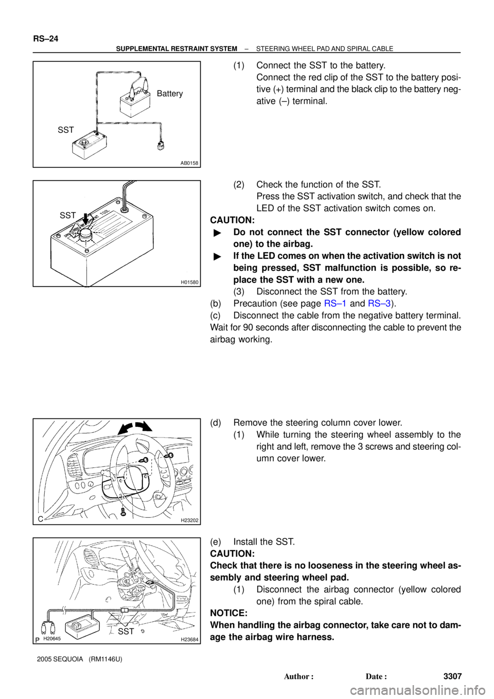
(1) Connect the SST to the battery.
Connect the red clip of the SST to the battery posi-
tive (+) terminal and the black clip to the battery neg-
ative (±) terminal.
(2) Check the function of the SST.
Press the SST activation switch, and check that the
LED of the SST activation switch comes on.
CAUTION:
�Do not connect the SST connector (yellow colored
one) to the airbag.
�If the LED comes on when the activation switch is not
being pressed, SST malfunction is possible, so re-
place the SST with a new one.
(3) Disconnect the SST from the battery.
(b) Precaution (see page RS±1 and RS±3).
(c) Disconnect the cable from the negative battery terminal.
Wait for 90 seconds after disconnecting the cable to prevent the
airbag working.
(d) Remove the steering column cover lower.
(1) While turning the steering wheel assembly to the
right and left, remove the 3 screws and steering col-
umn cover lower.
(e) Install the SST.
CAUTION:
Check that there is no looseness in the steering wheel as-
sembly and steering wheel pad.
(1) Disconnect the airbag connector (yellow colored
one) from the spiral cable.
NOTICE:
When handling the airbag connector, take care not to dam-
age the airbag wire harness.
Page 3317 of 4323

AB0152
SST
AB0163
Wire Harness
Diameter
Stripped Wire Harness Section
H23203
L
M
H23207
SST
RS±26
± SUPPLEMENTAL RESTRAINT SYSTEMSTEERING WHEEL PAD AND SPIRAL CABLE
3309 Author�: Date�:
2005 SEQUOIA (RM1146U)
(a) Check the function of the SST (see step 1±(a)).
(b) Remove the steering wheel pad (see page SR±14).
CAUTION:
�When removing the steering wheel pad, work must be
started 90 seconds after the ignition switch is turned
to the ºLOCKº position and the negative (±) terminal
cable is disconnected from the battery.
�When storing the steering wheel pad, keep the airbag
deployment side facing upward.
(c) Using a service±purpose wire harness for the vehicle, tie
down the steering wheel pad to the disc wheel.
Wire harness: Stripped wire harness section
1.25 mm
2
or more (0.0019 in2. or more).
CAUTION:
If the wire harness is too thin or an alternative object is
used to tie down the steering wheel pad, it may be snapped
by the shock when the airbag is deployed. Always use a
wire harness for vehicle use with an area of at least 1.25
mm
2
(0.0019 in.2).
HINT:
To calculate the area of the stripped wire harness section:
Area = 3.14 x (Diameter)
2
divided by 4
(1) Install the 2 bolts with washers into the 2 bolt holes
on the steering wheel pad.
Bolt:
L: 35.0 mm (1.378 in.)
M: 6.0 mm (0.236 in.)
Pitch: 1.0 mm (0.039 in.)
NOTICE:
�Tighten the bolts by hand until the bolts become diffi-
cult to turn.
�Do not tighten the bolts excessively.
(2) After connecting the SST below to each other, con-
nect them to the steering wheel pad connectors.
SST 09082±00802 (09082±10801, 09082±30801)
Page 3321 of 4323
RS0BC±08
RS±30
± SUPPLEMENTAL RESTRAINT SYSTEMSTEERING WHEEL PAD AND SPIRAL CABLE
3313 Author�: Date�:
2005 SEQUOIA (RM1146U)
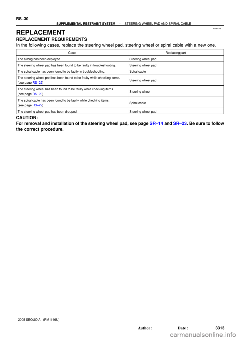
REPLACEMENT
REPLACEMENT REQUIREMENTS
In the following cases, replace the steering wheel pad, steering wheel or spiral cable with a new one.
CaseReplacing part
The airbag has been deployed.Steering wheel pad
The steering wheel pad has been found to be faulty in troubleshooting.Steering wheel pad
The spiral cable has been found to be faulty in troubleshooting.Spiral cable
The steering wheel pad has been found to be faulty while checking items.
(see page RS±22)Steering wheel pad
The steering wheel has been found to be faulty while checking items.
(see page RS±22)Steering wheel
The spiral cable has been found to be faulty while checking items.
(see page RS±22)Spiral cable
The steering wheel pad has been dropped.Steering wheel pad
CAUTION:
For removal and installation of the steering wheel pad, see page SR±14 and SR±23. Be sure to follow
the correct procedure.
Page 3322 of 4323
RS0BD±11
± SUPPLEMENTAL RESTRAINT SYSTEMSTEERING WHEEL PAD AND SPIRAL CABLE
RS±31
3314 Author�: Date�:
2005 SEQUOIA (RM1146U)
INSTALLATION
CAUTION:
�If the steering wheel pad has been dropped, or there are cracks, dents or other defects in the
case or connector, replace the steering wheel pad with a new one.
�When installing the steering wheel pad, take care it is not pinched between other parts.
�Never use airbag parts from another vehicle. When replacing parts, replace them with new
ones.
1. INSTALL SPIRAL CABLE (SEE PAGE SR±23)
2. INSTALL STEERING COLUMN COVER LOWER (SEE PAGE SR±23)
3. INSTALL STEERING WHEEL (SEE PAGE SR±23)
4. INSTALL STEERING WHEEL PAD (SEE PAGE SR±23)
5. CONNECT CABLE TO NEGATIVE BATTERY TERMINAL
6. PERFORM INITIALIZATION (SEE PAGE SR±23)
Some system need initialization when disconnecting the cable from the negative battery terminal.
7. INSPECT SRS WARNING LIGHT (SEE PAGE DI±1137)
Page 3324 of 4323
RS0T6±03
H23215
± SUPPLEMENTAL RESTRAINT SYSTEMFRONT PASSENGER AIRBAG ASSEMBLY
RS±33
3316 Author�: Date�:
2005 SEQUOIA (RM1146U)
REMOVAL
NOTICE:
�If the wiring connector of the SRS is disconnected
and the ignition switch is in the ON or ACC position,
DTCs will be recorded.
�Never use airbag parts from another vehicle. When
replacing parts, replace them with new ones.
1. PRECAUTION (SEE PAGE RS±1 and RS±3)
2. DISCONNECT CABLE FROM NEGATIVE BATTERY
TERMINAL
Wait for 90 seconds after disconnecting the cable to prevent the
airbag working.
3. REMOVE FRONT DOOR SCUFF PLATES
(SEE PAGE BO±89)
4. REMOVE COWL SIDE TRIM BOARDS
(SEE PAGE BO±89)
5. REMOVE SIDE PANELS (SEE PAGE BO±89)
6. REMOVE LOWER FINISH PANEL
(SEE PAGE BO±89)
7. REMOVE GLOVE COMPARTMENT DOOR
(SEE PAGE BO±89)
8. REMOVE LOWER NO. 2 FINISH PANEL
(SEE PAGE BO±89)
9. REMOVE SHIFTING HOLE COVER
(SEE PAGE BO±89)
10. REMOVE UPPER CONSOLE PANEL
(SEE PAGE BO±89)
11. REMOVE REAR CONSOLE BOX
(SEE PAGE BO±89)
12. REMOVE FRONT CONSOLE BOX
(SEE PAGE BO±89)
13. REMOVE LOWER INSTRUMENT COVER
(SEE PAGE BO±89)
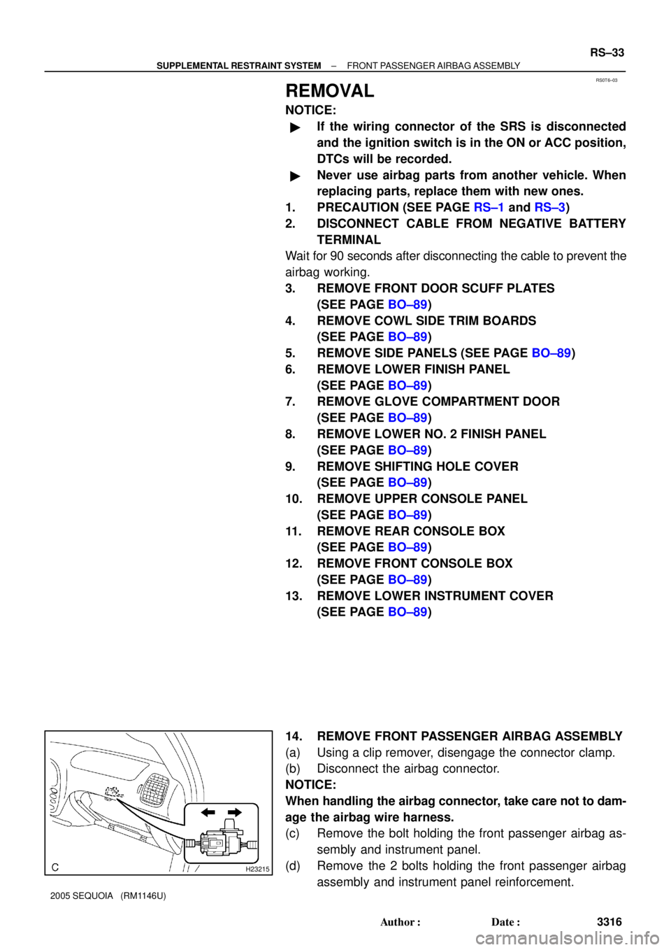
14. REMOVE FRONT PASSENGER AIRBAG ASSEMBLY
(a) Using a clip remover, disengage the connector clamp.
(b) Disconnect the airbag connector.
NOTICE:
When handling the airbag connector, take care not to dam-
age the airbag wire harness.
(c) Remove the bolt holding the front passenger airbag as-
sembly and instrument panel.
(d) Remove the 2 bolts holding the front passenger airbag
assembly and instrument panel reinforcement.
Page 3326 of 4323
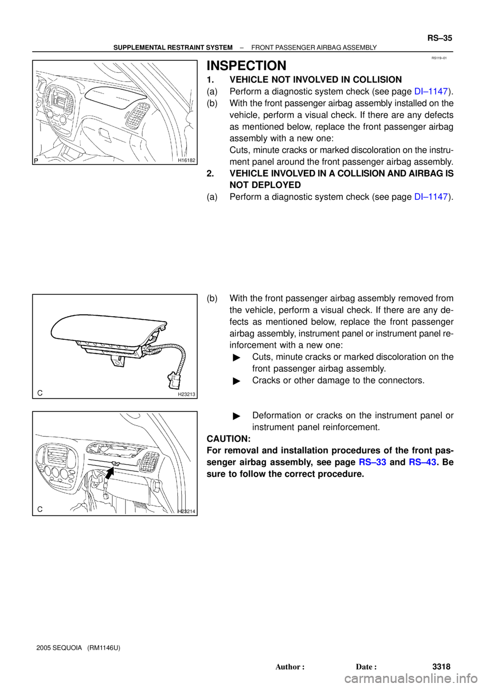
RS119±01
H16182
H23213
H23214
± SUPPLEMENTAL RESTRAINT SYSTEMFRONT PASSENGER AIRBAG ASSEMBLY
RS±35
3318 Author�: Date�:
2005 SEQUOIA (RM1146U)
INSPECTION
1. VEHICLE NOT INVOLVED IN COLLISION
(a) Perform a diagnostic system check (see page DI±1147).
(b) With the front passenger airbag assembly installed on the
vehicle, perform a visual check. If there are any defects
as mentioned below, replace the front passenger airbag
assembly with a new one:
Cuts, minute cracks or marked discoloration on the instru-
ment panel around the front passenger airbag assembly.
2. VEHICLE INVOLVED IN A COLLISION AND AIRBAG IS
NOT DEPLOYED
(a) Perform a diagnostic system check (see page DI±1147).
(b) With the front passenger airbag assembly removed from
the vehicle, perform a visual check. If there are any de-
fects as mentioned below, replace the front passenger
airbag assembly, instrument panel or instrument panel re-
inforcement with a new one:
�Cuts, minute cracks or marked discoloration on the
front passenger airbag assembly.
�Cracks or other damage to the connectors.
�Deformation or cracks on the instrument panel or
instrument panel reinforcement.
CAUTION:
For removal and installation procedures of the front pas-
senger airbag assembly, see page RS±33 and RS±43. Be
sure to follow the correct procedure.
Page 3328 of 4323

AB0158
SSTBattery
H23215
H23216SST
R13455
10 m (33 ft) or more
SSTBattery
± SUPPLEMENTAL RESTRAINT SYSTEMFRONT PASSENGER AIRBAG ASSEMBLY
RS±37
3320 Author�: Date�:
2005 SEQUOIA (RM1146U)
1. AIRBAG DEPLOYMENT WHEN SCRAPPING VE-
HICLE
(a) Check the function of the SST (see step 1±(a) on page
RS±23).
(b) Precaution (see page RS±1 and RS±3).
(c) Disconnect the cable from the negative battery terminal.
Wait for 90 seconds after disconnecting the cable to prevent the
airbag working.
(d) Remove the glove compartment door (see page
BO±89).
(e) Remove the lower No. 2 finish panel (see page
BO±89).
(f) Disconnect the airbag connector (yellow colored one)
from the front passenger airbag assembly.
(1) Using a clip remover, disengage the connector
clamp.
(2) Disconnect the airbag connector.
NOTICE:
When handling the airbag connector, take care not to dam-
age the airbag wire harness.
(g) Install the SST.
(1) Connect the SST connector to the front passenger
airbag assembly.
SST 09082±00700, 09082±00780
NOTICE:
To avoid damaging the SST connector and wire harness,
do not lock the secondary lock of the twin lock.
(2) Move the SST at least 10 m (33 ft) away from the ve-
hicle side window.
(3) Maintaining enough clearance for the SST wire har-
ness in the front side window, close all doors and
windows of the vehicle.
NOTICE:
Take care not to damage the SST wire harness.
(4) Connect the red clip of the SST to the battery posi-
tive (+) terminal and the black clip of the SST to the
negative (±) terminal.