Page 3106 of 4323
SA17X±07
SA±102
± SUSPENSION AND AXLEREAR AXLE SHAFT
3098 Author�: Date�:
2005 SEQUOIA (RM1146U)
INSTALLATION
Installation is in the reverse order of removal (See page SA±95).
HINT:
After installation, fill the brake reservoir with brake fluid, bleed the brake system (See page BR±4), check
for leaks and check the speed sensor signal (See page DI±899).
Page 3107 of 4323
SA24C±02
F14274
F14290
Nut
Washer
± SUSPENSION AND AXLEREAR WHEEL HUB BOLT
SA±103
3099 Author�: Date�:
2005 SEQUOIA (RM1146U)
REAR WHEEL HUB BOLT
REPLACEMENT
1. REMOVE REAR WHEEL
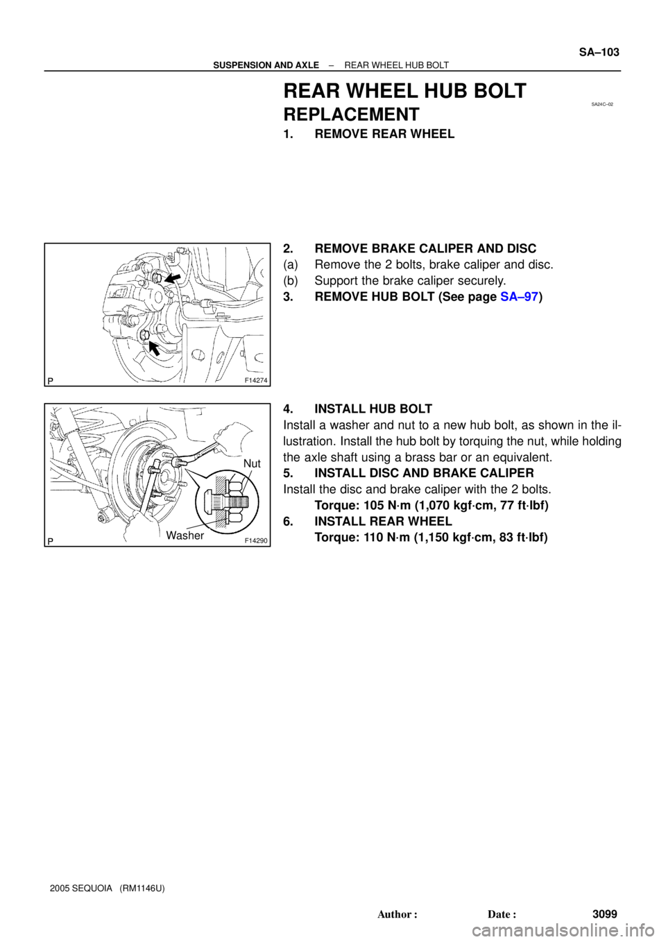
2. REMOVE BRAKE CALIPER AND DISC
(a) Remove the 2 bolts, brake caliper and disc.
(b) Support the brake caliper securely.
3. REMOVE HUB BOLT (See page SA±97)
4. INSTALL HUB BOLT
Install a washer and nut to a new hub bolt, as shown in the il-
lustration. Install the hub bolt by torquing the nut, while holding
the axle shaft using a brass bar or an equivalent.
5. INSTALL DISC AND BRAKE CALIPER
Install the disc and brake caliper with the 2 bolts.
Torque: 105 N´m (1,070 kgf´cm, 77 ft´lbf)
6. INSTALL REAR WHEEL
Torque: 110 N´m (1,150 kgf´cm, 83 ft´lbf)
Page 3108 of 4323
SA15K±09
F14321
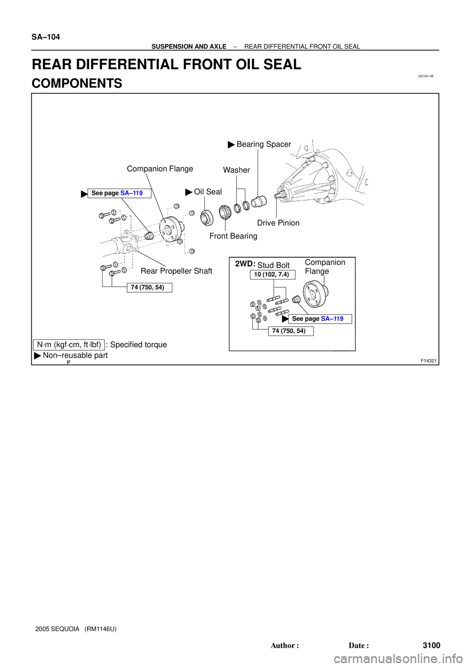
� Oil Seal
Front Bearing
� Bearing Spacer
N´m (kgf´cm, ft´lbf) : Specified torque
� Non±reusable partCompanion Flange
Rear Propeller ShaftWasher
�
74 (750, 54)
Drive Pinion
2WD:
10 (102, 7.4)
74 (750, 54)
�See page SA±119
Stud BoltCompanion
Flange
See page SA±119
SA±104
± SUSPENSION AND AXLEREAR DIFFERENTIAL FRONT OIL SEAL
3100 Author�: Date�:
2005 SEQUOIA (RM1146U)
REAR DIFFERENTIAL FRONT OIL SEAL
COMPONENTS
Page 3109 of 4323
SA24D±04
F14486
40 mm
(1.57 in.)
F14485
SST
F14484
SST
± SUSPENSION AND AXLEREAR DIFFERENTIAL FRONT OIL SEAL
SA±105
3101 Author�: Date�:
2005 SEQUOIA (RM1146U)
REPLACEMENT
1. DRAIN DIFFERENTIAL OIL
2. DISCONNECT REAR PROPELLER SHAFT
2WD: See page PR±3
4WD: See page PR±7
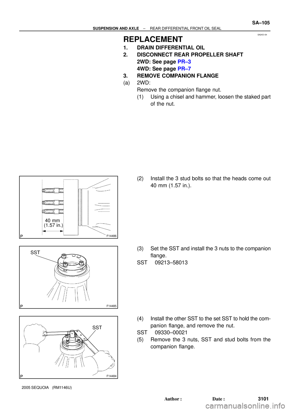
3. REMOVE COMPANION FLANGE
(a) 2WD:
Remove the companion flange nut.
(1) Using a chisel and hammer, loosen the staked part
of the nut.
(2) Install the 3 stud bolts so that the heads come out
40 mm (1.57 in.).
(3) Set the SST and install the 3 nuts to the companion
flange.
SST 09213±58013
(4) Install the other SST to the set SST to hold the com-
panion flange, and remove the nut.
SST 09330±00021
(5) Remove the 3 nuts, SST and stud bolts from the
companion flange.
Page 3112 of 4323
FA1083
SST
FA1084
R13337
Less than
5 mm (0.20 in.) SA±108
± SUSPENSION AND AXLEREAR DIFFERENTIAL FRONT OIL SEAL
3104 Author�: Date�:
2005 SEQUOIA (RM1146U)
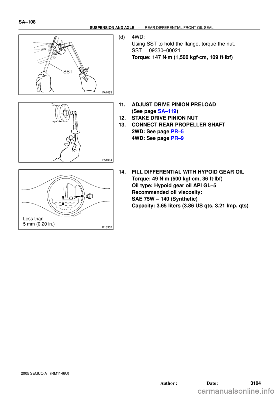
(d) 4WD:
Using SST to hold the flange, torque the nut.
SST 09330±00021
Torque: 147 N´m (1,500 kgf´cm, 109 ft´lbf)
11. ADJUST DRIVE PINION PRELOAD
(See page SA±119)
12. STAKE DRIVE PINION NUT
13. CONNECT REAR PROPELLER SHAFT
2WD: See page PR±5
4WD: See page PR±9
14. FILL DIFFERENTIAL WITH HYPOID GEAR OIL
Torque: 49 N´m (500 kgf´cm, 36 ft´lbf)
Oil type: Hypoid gear oil API GL±5
Recommended oil viscosity:
SAE 75W ± 140 (Synthetic)
Capacity: 3.65 liters (3.86 US qts, 3.21 Imp. qts)
Page 3114 of 4323
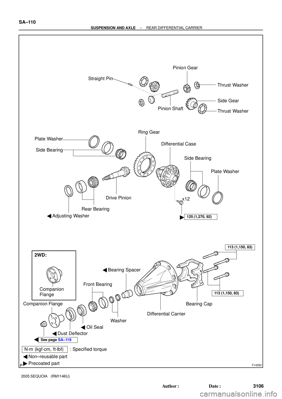
F14292
N´m (kgf´cm, ft´lbf) : Specified torqueStraight Pin
Pinion ShaftPinion Gear
Thrust Washer
Side Gear
Ring Gear
� Differential Case
Drive Pinion
Rear Bearing
� Adjusting Washer
� Bearing Spacer
Front Bearing
� Dust Deflector Companion Flange
Bearing CapThrust Washer
Plate Washer
Side Bearing
Side Bearing
Plate Washer
Differential Carrier
Washer
��Oil Seal
x12
125 (1,270, 92)
113 (1,150, 83)
113 (1,150, 83)
See page SA±119
� Non±reusable part
� Precoated part
Companion
Flange
2WD: SA±110
± SUSPENSION AND AXLEREAR DIFFERENTIAL CARRIER
3106 Author�: Date�:
2005 SEQUOIA (RM1146U)
Page 3115 of 4323

REMOVAL
1. REMOVE 2 REAR WHEELS
Torque: 110 N´m (1,122 kgf´cm")
SA24E±02
F14273
SST
F14274
F14276
± SUSPENSION AND AXLEREAR DIFFERENTIAL CARRIER
SA±111
3107 Author�: Date�:
2005 SEQUOIA (RM1146U)
REMOVAL
1. REMOVE 2 REAR WHEELS
Torque: 110 N´m (1,122 kgf´cm, 81 ft´lbf)
2. DRAIN HYPOID GEAR OIL
Torque: 49 N´m (500 kgf´cm, 36 ft´lbf)
3. DISCONNECT BRAKE LINES
(a) Using SST, disconnect the brake line and remove the clip.
SST 09023±00100
Torque: 15.5 N´m (158 kgf´cm, 11 ft´lbf)
(b) Use the same procedure described above to the other
side.
4. REMOVE BRAKE CALIPER AND DISC
(a) Remove the 2 bolts, brake caliper and disc.
Torque: 105 N´m (1,070 kgf´cm, 77 ft´lbf)
(b) Use the same procedure described above to the other
side.
5. REMOVE PARKING BRAKE ASSEMBLY
(a) Remove the parking brake assembly (See page
BR±43).
(b) Remove the 2 bolts and pull out the parking brake cable
from the backing plate.
Torque: 8.0 N´m (82 kgf´cm, 71 in.´lbf)
(c) Use the same procedures described above to the other
side.
6. REMOVE AXLE SHAFTS
(a) Remove the 4 nuts.
Torque: 122 N´m (1,244 kgf´cm, 90 ft´lbf)
(b) Pull out the axle shaft and remove the O±ring.
NOTICE:
Be careful not to damage the oil seal.
(c) Use the same procedures described above to the other
side.
Page 3117 of 4323

SA24F±03
R04321
R04322
R04463
± SUSPENSION AND AXLEREAR DIFFERENTIAL CARRIER
SA±113
3109 Author�: Date�:
2005 SEQUOIA (RM1146U)
DISASSEMBLY
1. CHECK COMPANION FLANGE RUNOU")
W00493
35 mm (1.38 in.)
SA24F±03
R04321
R04322
R04463
± SUSPENSION AND AXLEREAR DIFFERENTIAL CARRIER
SA±113
3109 Author�: Date�:
2005 SEQUOIA (RM1146U)
DISASSEMBLY
1. CHECK COMPANION FLANGE RUNOUT
Using a dial indicator, measure the vertical and lateral runout of
the companion flange.
Maximum: runout: 0.09 mm (0.0035 in.)
If the runout exceeds the maximum, replace the companion
flange.
2. CHECK RING GEAR RUNOUT
Using a dial indicator, measure the ring gear runout.
Maximum runout: 0.05 mm (0.0020 in.)
If the runout exceeds the maximum, replace the ring gear.
3. CHECK RING GEAR BACKLASH
Using a dial indicator, while holding the companion flange, mea-
sure the ring gear backlash.
Backlash: 0.13 ± 0.18 mm (0.0051 ± 0.0071 in.)
HINT:
Measure at 3 or more positions around the circumference of the
ring gear.
If the backlash is not within the specified value, adjust the side
bearing preload or repair as necessary.
4. CHECK TOOTH CONTACT BETWEEN RING GEAR
AND DRIVE PINION (See page SA±119)
5. CHECK SIDE GEAR BACKLASH
Using a dial indicator, measure the side gear backlash while
holding one pinion gear toward the case.
Backlash: 0.05 ± 0.20 mm (0.0020 ± 0.0079 in.)
If the backlash is not within the specified value, replace the side
gear thrust washer of the different thickness (See page
SA±119).