Page 3041 of 4323
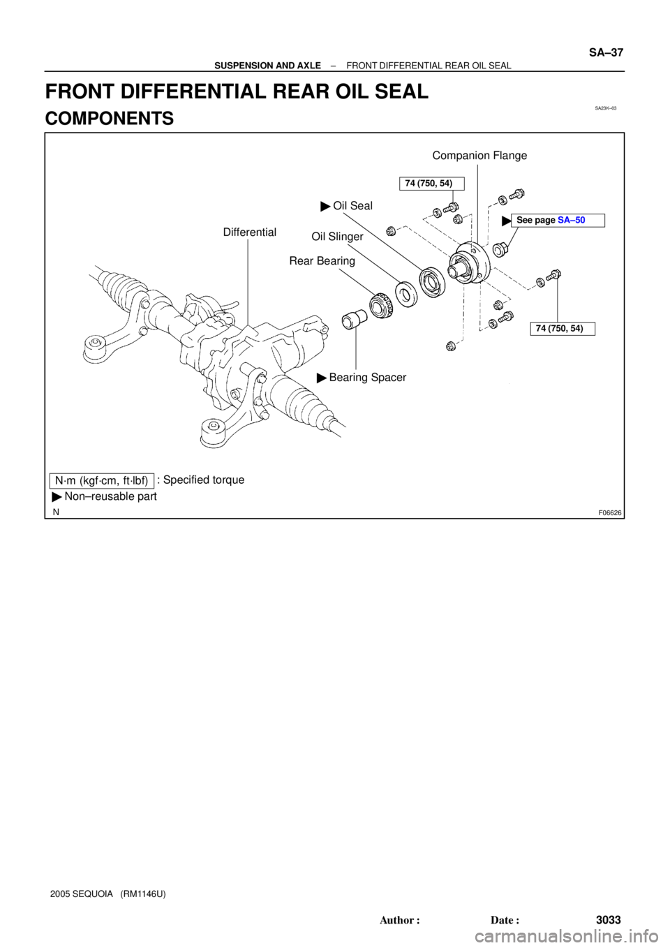
SA23K±03
F06626
� Non±reusable part� Bearing Spacer
N´m (kgf´cm, ft´lbf): Specified torque
Differential
� Oil Seal
Oil Slinger
Rear Bearing
74 (750, 54)
Companion Flange
74 (750, 54)
�See page SA±50
± SUSPENSION AND AXLEFRONT DIFFERENTIAL REAR OIL SEAL
SA±37
3033 Author�: Date�:
2005 SEQUOIA (RM1146U)
FRONT DIFFERENTIAL REAR OIL SEAL
COMPONENTS
Page 3042 of 4323
SA23L±04
Z00638
SST
R13369
SST
R13370
SST
R13371
SST SA±38
± SUSPENSION AND AXLEFRONT DIFFERENTIAL REAR OIL SEAL
3034 Author�: Date�:
2005 SEQUOIA (RM1146U)
REPLACEMENT
1. REMOVE ENGINE UNDER COVER
2. DRAIN DIFFERENTIAL OIL
3. REMOVE FRONT PROPELLER SHAFT
(See page PR±7)
4. REMOVE COMPANION FLANGE
(a) Using a chisel and hammer, loosen the staked part of the
nut.
(b) Using SST to hold the flange, remove the nut.
SST 09330±00021
(c) Using SST, remove the companion flange.
SST 09950±30012 (09951±03010, 09953±03010,
09954±03010, 09955±03030, 09956±03020)
5. REMOVE OIL SEAL AND OIL SLINGER
(a) Using SST, remove the oil seal.
SST 09308±10010
(b) Remove the oil slinger.
6. REMOVE REAR BEARING AND BEARING SPACER
(a) Using SST, remove the rear bearing from the drive pinion.
SST 09556±22010
(b) Remove the bearing spacer.
7. INSTALL BEARING SPACER, REAR BEARING AND
OIL SLINGER
(a) Install a new bearing spacer and place the rear bearing
and oil slinger.
Page 3043 of 4323

FA1083
SST
FA1084
R13338
Less than
5 mm (0.20 in.)
± SUSPENSION AND AXLEFRONT DIFFERENTIAL REAR OIL SEAL
SA±39
3035 Author�: Date�:
2005 SE")
R13368
SST
R13374
SST
4.5 ± 0.3 mm
(0.177 ± 0.012 in.)
FA1083
SST
FA1084
R13338
Less than
5 mm (0.20 in.)
± SUSPENSION AND AXLEFRONT DIFFERENTIAL REAR OIL SEAL
SA±39
3035 Author�: Date�:
2005 SEQUOIA (RM1146U)
(b) Using SST and the companion flange, install the rear
bearing, then remove the companion flange.
SST 09950±30012 (09951±03010, 09953±03010,
09954±03010, 09955±03030, 09956±03020)
8. INSTALL OIL SEAL
(a) Coat a new oil seal lip with MP grease.
(b) Using SST and a hammer, install the oil seal.
SST 09554±22010
Oil seal drive in depth: 4.5 ± 0.3 mm (0.177 ± 0.012 in.)
9. INSTALL COMPANION FLANGE
(a) Place the companion flange on the drive pinion.
(b) Coat the threads of a new nut with hypoid gear oil.
(c) Using SST to hold the flange, torque the nut.
SST 09330±00021
Torque: 108 N´m (1,100 kgf´cm, 80 ft´lbf)
10. ADJUST DRIVE PINION PRELOAD
(See page SA±50)
11. STAKE DRIVE PINION NUT
12. INSTALL FRONT PROPELLER SHAFT
(See page PR±9)
13. FILL DIFFERENTIAL WITH HYPOID GEAR OIL
Torque: 39 N´m (400 kgf´cm, 29 ft´lbf)
Oil type: Hypoid gear oil API GL±5
Recommended oil viscosity: SAE 75W±90
Capacity: 1.15 liters (1.22 US qts, 1.01 Imp. qts)
14. INSTALL ENGINE UNDER COVER
Page 3046 of 4323
SA24Q±02
F06630
SA±42
± SUSPENSION AND AXLEFRONT DIFFERENTIAL CARRIER
3038 Author�: Date�:
2005 SEQUOIA (RM1146U)
REMOVAL
1. DRAIN DIFFERENTIAL OIL
2. REMOVE DRIVE SHAFTS (See page SA±31)
3. DISCONNECT FRONT PROPELLER SHAFT
(See page PR±7)
HINT:
Support the front propeller shaft securely.
4. REMOVE TUBE WITH WIRE HARNESS ASSEMBLY
(a) Disconnect the breather hose, vacuum hose and actuator
connector.
(b) Remove the bolt and tube with wire harness assembly.
5. REMOVE FRONT DIFFERENTIAL CARRIER
(a) Support the front differential with a jack.
(b) Using a hexagon (12 mm) wrench, remove the rear
mounting nut.
(c) Remove the 2 front mounting bolts.
(d) Lower the jack and remove the front differential carrier.
6. REMOVE DIFFERENTIAL MOUNTING CUSHIONS
(a) Remove the 2 bolts and rear mounting cushion.
(b) Remove the 5 bolts and 2 front mounting cushions.
Page 3059 of 4323

Z00699
Heel ContactFace Contact
Proper ContactSelect an adjusting washer that will bring the
drive pinion closer to the ring gear.
Toe Contact
Flank Contact
Select an adjusting washer that will shift the
drive pinion away from the ring gear.
FA2008
Washer
± SUSPENSION AND AXLEFRONT DIFFERENTIAL CARRIER
SA±55
3051 Author�: Date�:
2005 SEQUOIA (RM1146U)
If the teeth are not contacting properly, use the following table
to select a proper washer for correction.
Washer thickness:
Thickness mm (in.)Thickness mm (in.)Thickness mm (in.)
1.69 ± 1.71 (0.0665 ± 0.0673)1.93 ± 1.95 (0.0760 ± 0.0768)2.17 ± 2.19 (0.0854 ± 0.0862)
1.72 ± 1.74 (0.0677 ± 0.0685)1.96 ± 1.98 (0.0772 ± 0.0780)2.20 ± 2.22 (0.0866 ± 0.0874)
1.75 ± 1.77 (0.0689 ± 0.0697)1.99 ± 2.01 (0.0783 ± 0.0791)2.23 ± 2.25 (0.0878 ± 0.0886)
1.78 ± 1.80 (0.0701 ± 0.0709)2.02 ± 2.04 (0.0795 ± 0.0803)2.26 ± 2.28 (0.0890 ± 0.0898)
1.81 ± 1.83 (0.0713 ± 0.0720)2.05 ± 2.07 (0.0807 ± 0.0815)2.29 ± 2.31 (0.0902 ± 0.0909)
1.84 ± 1.86 (0.0724 ± 0.0732)2.08 ± 2.10 (0.0819 ± 0.0827)2.32 ± 2.34 (0.0913 ± 0.0921)
1.87 ± 1.89 (0.0736 ± 0.0744)2.11 ± 2.13 (0.0831 ± 0.0839)±
1.90 ± 1.92 (0.0748 ± 0.0756)2.14 ± 2.16 (0.0843 ± 0.0850)±
14. REMOVE COMPANION FLANGE AND OIL SLINGER
(See page SA±43)
15. REMOVE REAR BEARING (See page SA±43)
16. INSTALL NEW BEARING SPACER, REAR BEARING
AND OIL SLINGER
(a) Install a new bearing spacer and place the rear bearing
and oil slinger.
Page 3061 of 4323

20. INSTALL DIFFERENTIAL CASE
21. INSTALL SIDE BEARING RETAINER
(a)")
R13200
FIPG
R13416
SST
R13415
± SUSPENSION AND AXLEFRONT DIFFERENTIAL CARRIER
SA±57
3053 Author�: Date�:
2005 SEQUOIA (RM1146U)
20. INSTALL DIFFERENTIAL CASE
21. INSTALL SIDE BEARING RETAINER
(a) Remove any old FIPG material and be careful not to drop
oil on the contact surfaces of the differential carrier and
side bearing retainer.
(b) Clean both installation surfaces with gasoline or alcohol.
(c) Apply FIPG to the side bearing retainer, as shown in the
illustration.
FIPG:
Part No. 08826±00090, THREE BOND 1281 or
equivalent
HINT:
Install the side bearing retainer within 10 minutes after applying
FIPG.
(d) Install the side bearing retainer with the 10 bolts.
Torque: 69 N´m (700 kgf´cm, 51 ft´lbf)
22. CHECK TOTAL PRELOAD (See step 12.)
23. RECHECK RING GEAR BACKLASH
(See page SA±43)
24. RECHECK TOOTH CONTACT BETWEEN RING GEAR
AND DRIVE PINION (See step 13.)
25. CHECK COMPANION FLANGE RUNOUT
(See step 1.)
26. STAKE DRIVE PINION NUT
27. INSTALL SIDE OIL SEAL
(a) Using SST and a plastic hammer, install a new oil seal un-
til its surface is flush with the differential carrier end.
SST 09608±32010
(b) Coat the oil seal lip with MP grease.
28. INSTALL INTERMEDIATE SHAFT NO. 1
(a) Install a new snap ring to the shaft.
(b) Using a plastic hammer, install the shaft to the differential
case.
(c) Check that the intermediate shaft will not come out by try-
ing to pull it out by hand.
Page 3063 of 4323

INSTALLATION
1. INSTALL DIFFERENTIAL MOUNTING CUSHIONS
(a) Install the 2 front mounting")
SA14Q±06
± SUSPENSION AND AXLEFRONT DIFFERENTIAL CARRIER
SA±59
3055 Author�: Date�:
2005 SEQUOIA (RM1146U)
INSTALLATION
1. INSTALL DIFFERENTIAL MOUNTING CUSHIONS
(a) Install the 2 front mounting cushions with the 5 bolts.
Torque: 157 N´m (1,600 kgf´cm, 116 ft´lbf)
(b) Install the rear mounting cushion with the 2 bolts.
Torque: 108 N´m (1,100 kgf´cm, 80 ft´lbf)
2. INSTALL FRONT DIFFERENTIAL CARRIER
(a) Jack up the front differential.
(b) Install the 2 front mounting bolts.
Torque: 137 N´m (1,400 kgf´cm, 101 ft´lbf)
(c) Using a hexagon (12 mm) wrench, install the rear mounting nut.
Torque: 87 N´m (890 kgf´cm, 64 ft´lbf)
(d) Remove the jack.
3. INSTALL TUBE WITH WIRE HARNESS ASSEMBLY
(a) Install the tube with wire harness assembly with the bolt.
Torque: 13 N´m (130 kgf´cm, 9 ft´lbf)
(b) Connect the actuator connector, vacuum hose and breather hose.
4. CONNECT FRONT PROPELLER SHAFT (See page PR±9)
5. INSTALL DRIVE SHAFTS (See page SA±36)
6. FILL DIFFERENTIAL WITH HYPOID GEAR OIL (See page SA±38)
Page 3066 of 4323

(g) Push the 2WD/4HI switch and check that the 4WD indica-
tor ligh")
F16855
2WD/4HI Switch
SA0356
F06638
SA±62
± SUSPENSION AND AXLEA.D.D. CONTROL SYSTEM
3058 Author�: Date�:
2005 SEQUOIA (RM1146U)
(g) Push the 2WD/4HI switch and check that the 4WD indica-
tor light goes off after it is blinking.
(h) Check the A.D.D. actuator operation by sound.
(i) Disconnect the actuator connector.
(j) Check the continuity between each terminal, as shown in
the chart.
Tester connected terminal numberSpecified condition
1 ± 3Continuity
1 ± 4No continuity
3 ± 5No continuity
4 ± 5No continuity
(k) Connect the actuator connector.
4. INSPECT TRANSFER 4WD POSITION SWITCH
(See page TR±9)
5. REMOVE A.D.D. ACTUATOR (See page SA±43)
6. INSPECT CLUTCH HUB AND CLUTCH SLEEVE
(a) Check the clutch hub and clutch sleeve for wear and dam-
age.
If necessary, replace them.
(b) Check that clutch sleeve slides smoothly on the clutch
hub.
7. MEASURE SLEEVE FORK AND CLUTCH SLEEVE
CLEARANCE
Using a feeler gauge, measure the clearance between the
sleeve fork and clutch sleeve.
Maximum clearance: 0.35 mm (0.0138 in.)
If the clearance exceeds the maximum, replace the fork or
sleeve.