Page 2936 of 4323
AT13C±01
D05180
AT±20
± AUTOMATIC TRANSMISSION (A750E, A750F)COLUMN SHIFT ASSEMBLY
2928 Author�: Date�:
2005 SEQUOIA (RM1146U)
REMOVAL
1. REMOVE STEERING COLUMN ASSEMBLY
(See page SR±14)
2. REMOVE PARKING LOCK CABLE ASSEMBLY
(a) Remove the screw and parking lock cable No. 2.
(b) Using a torx® socket wrench, remove the 2 screws and
parking lock cable No. 1.
(c) Remove the spring.
(d) Remove the 2 bolts and parking lock cable housing.
3. REMOVE SHIFT LEVER
(a) Disconnect the connector.
(b) Using a torx® socket wrench, remove the torx® screw and
shift lever.
4. REMOVE SHIFT LEVER HOUSING
Using a torx® socket wrench, remove the 3 torx® screws and
shift lever housing.
Page 2938 of 4323
COLUMN SHIFT ASSEMBLY
2930 Author�: Date�:
2005 SEQUOIA (RM1146U)
(g) Install the parking lock cable No. 2 to column upper brack-
et with the cl")
D02002
AT±22
± AUTOMATIC TRANSMISSION (A750E, A750F)COLUMN SHIFT ASSEMBLY
2930 Author�: Date�:
2005 SEQUOIA (RM1146U)
(g) Install the parking lock cable No. 2 to column upper brack-
et with the clip.
(h) Install the cable end to the sliding block of the column up-
per bracket with the screw.
Torque: 2.2 N´m (23 kgf´cm, 19 in.´lbf)
(i) After installation, check the following items.
(1) When the pedal button is pushed, shift lever should
be locked.
(2) When the pedal button is released, shift lever
should be unlocked.
4. INSTALL STEERING COLUMN ASSEMBLY
(See page SR±23)
5. ADJUST CABLE HOUSING
(a) Shift the shift lever to the P position.
(b) Turn the ignition key to the LOCK position.
(c) Loosen the 2 bolts and adjust the cable housing.
HINT:
�Pedal button should touch the pedal plate cushion.
�Brake pedal should not be moved by the pedal button.
�Cable housing should not be toughed the brake pedal
and the brake pedal plate cushion.
(d) Torque the 2 bolts.
Torque: 10.5 N´m (110 kgf´cm, 8 ft´lbf)
6. CONFIRM SHIFT LOCK SYSTEM OPERATION
(a) Only when the brake pedal is engaged and the ignition
key is not in the LOCK position, the shift lever can be
shifted from the P position to other positions.
When the shift lever is in the P position and the brake ped-
al is released, the shift lever cannot be shifted from P posi-
tion to other positions.
(b) When the shift lever is not in the P position, the ignition
key cannot be turned to the LOCK position.
Only when the shift lever is in the P position, the ignition
key can be removed.
(c) Cable No. 1 and No. 2 should not be deformed by other
parts located around the steering column.
Page 2941 of 4323
AT13F±01
D13882
D13867
± AUTOMATIC TRANSMISSION (A750E, A750F)AUTOMATIC TRANSMISSION UNIT
AT±25
2933 Author�: Date�:
2005 SEQUOIA (RM1146U)
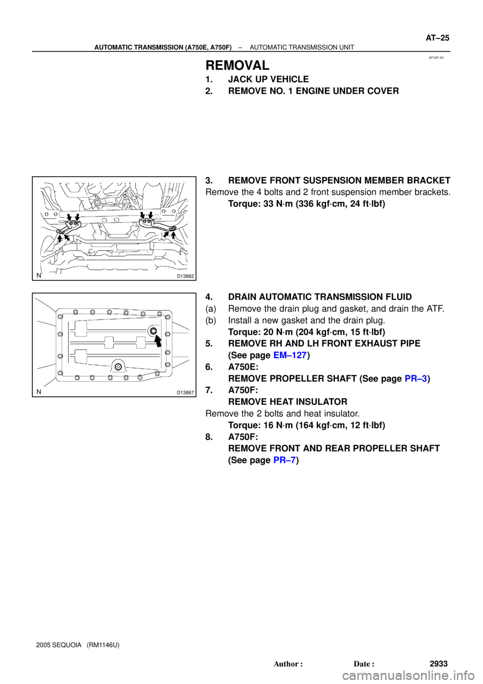
REMOVAL
1. JACK UP VEHICLE
2. REMOVE NO. 1 ENGINE UNDER COVER
3. REMOVE FRONT SUSPENSION MEMBER BRACKET
Remove the 4 bolts and 2 front suspension member brackets.
Torque: 33 N´m (336 kgf´cm, 24 ft´lbf)
4. DRAIN AUTOMATIC TRANSMISSION FLUID
(a) Remove the drain plug and gasket, and drain the ATF.
(b) Install a new gasket and the drain plug.
Torque: 20 N´m (204 kgf´cm, 15 ft´lbf)
5. REMOVE RH AND LH FRONT EXHAUST PIPE
(See page EM±127)
6. A750E:
REMOVE PROPELLER SHAFT (See page PR±3)
7. A750F:
REMOVE HEAT INSULATOR
Remove the 2 bolts and heat insulator.
Torque: 16 N´m (164 kgf´cm, 12 ft´lbf)
8. A750F:
REMOVE FRONT AND REAR PROPELLER SHAFT
(See page PR±7)
Page 2945 of 4323
AUTOMATIC TRANSMISSION UNIT
AT±29
2937 Author�: Date�:
2005 SEQUOIA (RM1146U)
INSTALLATION
1. CHECK TORQUE CONVERTER INS")
AT13G±01
D14133
A
D14130Dimension B
± AUTOMATIC TRANSMISSION (A750E, A750F)AUTOMATIC TRANSMISSION UNIT
AT±29
2937 Author�: Date�:
2005 SEQUOIA (RM1146U)
INSTALLATION
1. CHECK TORQUE CONVERTER INSTALLATION
(a) Install the torque converter to the transmission housing.
(b) Using vernier calipers and a straight edge, measure di-
mension A between the transmission fitting part and the
converter fitting part of the drive plate.
(c) Using vernier calipers and a straight edge, measure the
dimension B shown in the illustration and check that B is
greater than A measured in step (b).
Standard distance: A + 1 mm (0.04 in.) or more
2. MEASURE DRIVE PLATE RUNOUT AND INSPECT
RING GEAR (See page AT±30)
3. TRANSMISSION INSTALLATION
Installation is in the reverse order of removal (See page
AT±25).
HINT:
�After installation, adjust the shift lever position (See page
DI±524).
�Fill with ATF and check the fluid level (See page
DI±524).
Fluid type: Toyota genuine ATF WS
�Conduct the road test of the vehicle (See page DI±535).
Page 2946 of 4323
TORQUE CONVERTER CLUTCH AND DRIVE PLATE
2938 Author�: Date�:
2005 SEQUOIA (RM1146U)
TORQUE CONVE")
AT5436
SST
AT13H±01
AT5437
Hold
Turn
Free
Lock
Q04237
AT±30
± AUTOMATIC TRANSMISSION (A750E, A750F)TORQUE CONVERTER CLUTCH AND DRIVE PLATE
2938 Author�: Date�:
2005 SEQUOIA (RM1146U)
TORQUE CONVERTER CLUTCH
AND DRIVE PLATE
INSPECTION
1. INSPECT ONE±WAY CLUTCH
(a) Install SST so that it fits in the notch of the converter hub
and outer race of the one±way clutch.
SST 09350±30020 (09351±32020)
(b) Press on the serrations of the stator with a finger and ro-
tate it.
(c) Check if it rotates smoothly when turned clockwise and
locks when turned counterclockwise.
If necessary, clean the converter clutch and retest the one±way
clutch.
Replace the converter clutch if the clutch still fails the test.
2. MEASURE DRIVE PLATE RUNOUT AND INSPECT
RING GEAR
(a) Set up a dial indicator and measure the drive plate runout.
Maximum runout: 0.20 mm (0.0079 in.)
(b) Check for damage to the ring gear.
If runout is not within the specification or if the ring gear is dam-
aged, replace the drive plate. If installing a new drive plate, note
the orientation of the spacers and tighten the bolts (See page
EM±83 or EM±95).
Page 2947 of 4323
TR04G±02
± TRANSFERTRANSFER SYSTEM
TR±1
2939 Author�: Date�:
2005 SEQUOIA (RM1146U)
TRANSFER SYSTEM
PRECAUTION
NOTICE:
When disconnecting the battery terminal, initialize the following system after the terminal is recon-
nected.
System NameSee Page
Back Door Power Window Control SystemBE±77
When working with FIPG material, you must observe the following:
�Using a razor blade and gasket scraper, remove all the old FIPG material from gasket surfaces.
�Thoroughly clean all components to remove any loose material.
�Clean both sealing surfaces with a non±residue solvent.
�Apply FIPG in an approx. 1.2 mm (0.047 in.) wide bead along the sealing surface.
�Parts must be assembled within 10 minutes of FIPG application. Otherwise, the FIPG material
must be removed and reapplied.
Page 2948 of 4323

TROUBLESHOOTING
PROBLEM SYMPTOMS TABLE
Use the table below to help find the cause of the problem. The numbers i")
TR04H±04
TR±2
± TRANSFERTROUBLESHOOTING
2940 Author�: Date�:
2005 SEQUOIA (RM1146U)
TROUBLESHOOTING
PROBLEM SYMPTOMS TABLE
Use the table below to help find the cause of the problem. The numbers indicate the priority of the likely cause
of the problem. Check each part in order. If necessary, replace these parts.
SymptomSuspected AreaSee page
Noise
1. Oil (Level low)
2. Oil (Wrong)
3. Transfer faultyTR±5
TR±5
TR±7
Oil leakage
1. Oil (Level too high)
2. Gasket (Damaged)
3. Oil seal (Worn or damaged)
4. O±ring (Worn or damaged)TR±5
TR±7
TR±16
TR±7
Tight corner brakingCenter differential or transfer faultyTR±7
Shift from 2WD (H) to 4WD (H) impossible
1. 4WD fuse
2. Wire harness
3. Vehicle speed sensor
4. 2WD/4HI switch
5. 4WD indicator light
6. Actuator assembly
7. A.D.D. control system
8. 4WD control ECU
9. Transfer assembly±
±
BE±55
TR±39
TR±39
TR±39
SA±61
TR±39
TR±3
Shift from 2WD (H) to 4WD (L4) impossible
1. 4LO switch
2. Wire harness
3. 4WD control ECUTR±39
±
TR±39
Shift from 4WD (H) to 4WD (L4) impossible
1. 4LO switch
2. Wire harness
3. 4WD control ECUTR±9
±
TR±39
Shift from 4WD (H) to 2WD (H) impossible
1. 4WD fuse
2. Wire harness
3. 4WD indicator light
4. Actuator assembly
5. A.D.D. control system
6. 4WD control ECU
7. Transfer assembly±
±
TR±39
TR±39
SA±61
TR±39
TR±3
Shift from 4WD (L4) to 2WD (H) impossible
1. 2WD/4HI switch
2. Wire harness
3. 4WD control ECUTR±39
±
TR±39
Shift from 4WD (L4) to 4WD (H) impossible
1. 2WD/4HI switch
2. Wire harness
3. 4WD control ECUTR±39
±
TR±39
Page 2950 of 4323

REMOVAL
1. SWITCH TRANSFER TO 2WD
2. REMOVE PROTECTOR
Remove the 4 bolts and protector.
3. DRAIN TR")
TR0DD±01
F19315
F19237
TR±4
± TRANSFERTRANSFER UNIT
2942 Author�: Date�:
2005 SEQUOIA (RM1146U)
REMOVAL
1. SWITCH TRANSFER TO 2WD
2. REMOVE PROTECTOR
Remove the 4 bolts and protector.
3. DRAIN TRANSFER OIL
4. REMOVE FRONT SUSPENSION MEMBER BRACKET
Remove the 8 bolts and 2 front suspension member brackets.
5. REMOVE LH AND RH FRONT EXHAUST PIPES
(See page EM±126)
6. REMOVE FRONT AND REAR PROPELLER SHAFT
(See page PR±7)
7. REMOVE CROSS MEMBER
(a) Remove the 2 bolts and heat insulator.
(b) Support the rear side of the transmission with a transmis-
sion jack.
(c) Remove the 4 set bolts of the engine rear mounting.
(d) Remove the 4 bolts, nuts and cross member.
8. REMOVE ENGINE REAR MOUNTING
Remove the 4 bolts and engine rear mounting from the transfer.
9. DISCONNECT VEHICLE SPEED SENSOR AND
TRANSFER ACTUATOR CONNECTORS
10. REMOVE TRANSFER
(a) Support the transfer with another transmission jack.
(b) Remove the 8 transfer mounting bolts.
(c) Pull the transfer out from the transmission down and to-
ward the rear.