Page 2823 of 4323
SF0Q1±12
± SFIENGINE CONTROL MODULE (ECM)
SF±81
2815 Author�: Date�:
2005 SEQUOIA (RM1146U)
INSPECTION
1. DISCONNECT CABLE FROM NEGATIVE (±) BATTERY TERMINAL
2. REMOVE REMOVE GLOVE COMPARTMENT
(a) Remove the 2 screws and glove compartment door.
(b) Remove the 3 screws and lower No.2 finish panel.
3. REMOVE HEATER TO REGISTER DUCT
4. REMOVE ECM
(a) Disconnect the 5 connectors.
(b) Remove the 2 bolts and ECM.
5. INSPECT ECM (See page DI±34)
6. REINSTALL ECM
(a) Install the ECM with the 2 bolts.
(b) Connect the 5 connectors.
7. INSTALL HEATER TO REGISTER DUCT
8. INSTALL GLOVE COMPARTMENT
(a) Install the lower No.2 finish panel with 3 screws.
(b) Install the glove compartment door with the 2 screws.
9. CONNECT CABLE TO NEGATIVE (±) BATTERY TERMINAL
10. PERFORM INITIALIZATION (See page IN±20)
Some system need initialzation when disconnecting the cable from the battery terminal.
Page 2830 of 4323
CO0IR±06
B17478
B17479
CO±6
± COOLINGWATER PUMP
2822 Author�: Date�:
2005 SEQUOIA (RM1146U)
REMOVAL
1. DRAIN ENGINE COOLANT
2. REMOVE TIMING BELT (See page EM±16)
3. REMOVE NO.2 IDLER PULLEY (See page EM±16)
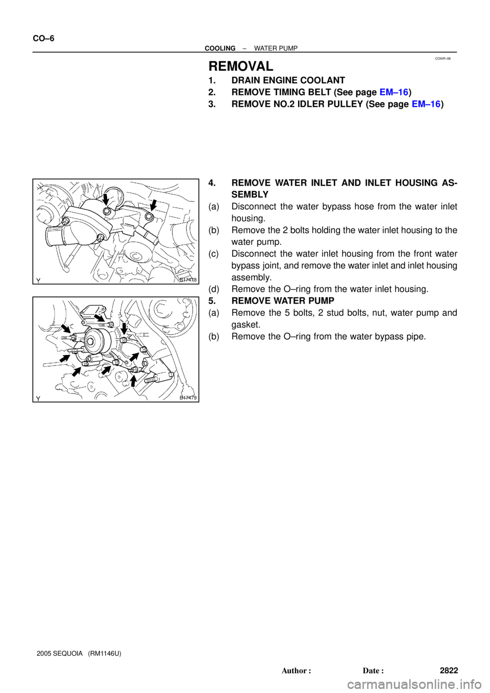
4. REMOVE WATER INLET AND INLET HOUSING AS-
SEMBLY
(a) Disconnect the water bypass hose from the water inlet
housing.
(b) Remove the 2 bolts holding the water inlet housing to the
water pump.
(c) Disconnect the water inlet housing from the front water
bypass joint, and remove the water inlet and inlet housing
assembly.
(d) Remove the O±ring from the water inlet housing.
5. REMOVE WATER PUMP
(a) Remove the 5 bolts, 2 stud bolts, nut, water pump and
gasket.
(b) Remove the O±ring from the water bypass pipe.
Page 2831 of 4323
CO0UZ±05
B04067Air HoleWa t e r
Hole
P21661
P21660
B07456
± COOLINGWATER PUMP
CO±7
2823 Author�: Date�:
2005 SEQUOIA (RM1146U)
INSPECTION
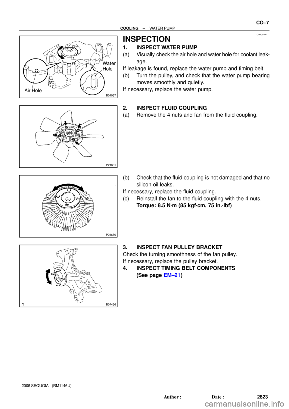
1. INSPECT WATER PUMP
(a) Visually check the air hole and water hole for coolant leak-
age.
If leakage is found, replace the water pump and timing belt.
(b) Turn the pulley, and check that the water pump bearing
moves smoothly and quietly.
If necessary, replace the water pump.
2. INSPECT FLUID COUPLING
(a) Remove the 4 nuts and fan from the fluid coupling.
(b) Check that the fluid coupling is not damaged and that no
silicon oil leaks.
If necessary, replace the fluid coupling.
(c) Reinstall the fan to the fluid coupling with the 4 nuts.
Torque: 8.5 N´m (85 kgf´cm, 75 in.´lbf)
3. INSPECT FAN PULLEY BRACKET
Check the turning smoothness of the fan pulley.
If necessary, replace the pulley bracket.
4. INSPECT TIMING BELT COMPONENTS
(See page EM±21)
Page 2833 of 4323
B17478
AB
± COOLINGWATER PUMP
CO±9
2825 Author�: Date�:
2005 SEQUOIA (RM1146U)
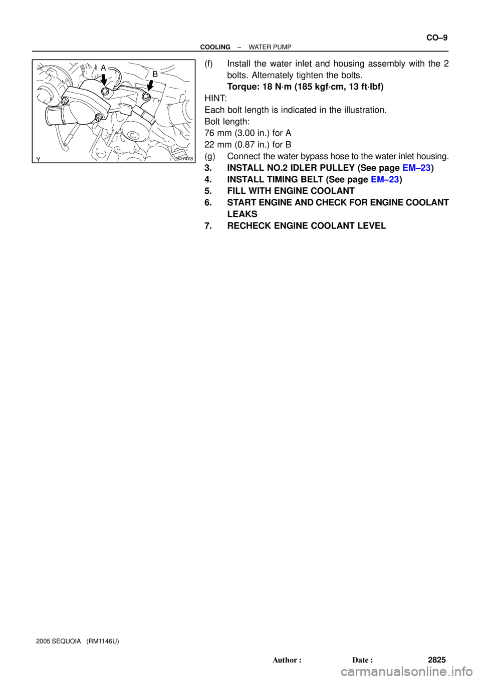
(f) Install the water inlet and housing assembly with the 2
bolts. Alternately tighten the bolts.
Torque: 18 N´m (185 kgf´cm, 13 ft´lbf)
HINT:
Each bolt length is indicated in the illustration.
Bolt length:
76 mm (3.00 in.) for A
22 mm (0.87 in.) for B
(g) Connect the water bypass hose to the water inlet housing.
3. INSTALL NO.2 IDLER PULLEY (See page EM±23)
4. INSTALL TIMING BELT (See page EM±23)
5. FILL WITH ENGINE COOLANT
6. START ENGINE AND CHECK FOR ENGINE COOLANT
LEAKS
7. RECHECK ENGINE COOLANT LEVEL
Page 2850 of 4323

REMOVAL
HINT:
When repairing the oil pump, the oil pan and strainer should be
removed an")
LU08Q±10
B05837
Pull O±Ring
B05838
LU±8
± LUBRICATIONOIL PUMP
2842 Author�: Date�:
2005 SEQUOIA (RM1146U)
REMOVAL
HINT:
When repairing the oil pump, the oil pan and strainer should be
removed and cleaned.
1. REMOVE ENGINE FROM VEHICLE
(2WD: See page EM±79)
(4WD: See page EM±92)
2. INSTALL ENGINE TO ENGINE STAND FOR DIS-
ASSEMBLY
3. REMOVE TIMING BELT (See page EM±16)
4. REMOVE NO.1 IDLER PULLEY (See page EM±16)
5. REMOVE NO.2 IDLER PULLEY (See page EM±16)
6. REMOVE CRANKSHAFT TIMING PULLEY
(See page EM±16)
7. REMOVE CRANKSHAFT POSITION SENSOR
(See page IG±11)
8. REMOVE OIL DIPSTICK AND GUIDE
(a) Remove the bolt holding the oil dipstick to the LH cylinder
head.
(b) Pull out the dipstick guide together with the dipstick from
the No.1 oil pan.
(c) Remove the O±ring from the dipstick guide.
9. REMOVE OIL FILTER, OIL COOLER AND FILTER
BRACKET ASSEMBLY
(a) Disconnect the oil pressure switch connector.
(b) Take out the vinyl tape, and disconnect the wire from the
clamp.
(c) Turn the clamp counterclockwise, and remove the clamp
from the oil filter bracket.
(d) Disconnect the oil cooler hose from the oil cooler.
(e) Remove the 2 bolts, nut, the oil filter, oil cooler and filter
bracket assembly.
(f) Remove the gasket from the filter bracket.
Page 2854 of 4323

INSPECTION
1. INSPECT RELIEF VALVE
Coat the valve with engine oil and check that it fa")
LU08S±07
B02609
B02613
B02614
B02615
LU±12
± LUBRICATIONOIL PUMP
2846 Author�: Date�:
2005 SEQUOIA (RM1146U)
INSPECTION
1. INSPECT RELIEF VALVE
Coat the valve with engine oil and check that it falls smoothly
into the valve hole by its own weight.
If it doesn't, replace the relief valve. If necessary, replace the oil
pump assembly.
2. INSPECT DRIVE AND DRIVEN ROTORS
(a) Place the drive and driven rotors into the oil pump body.
(see page LU±14)
(b) Inspect the rotors for the body clearance.
Using a feeler gauge, measure the clearance between
the drive and driven rotor tips.
Standard tip clearance:
0.060 to 0.180 mm (0.0024 to 0.0071 in.)
Maximum tip clearance: 0.18 mm (0.0071 in.)
If the tip clearance is greater than maximum, replace the rotors
as a set.
(c) Inspect the rotors for the side clearance.
Using a feeler gauge and precision straight edge, mea-
sure the clearance between the rotors and precision
straight edge.
Side clearance:
0.030 to 0.090 mm (0.0012 to 0.0035 in.)
Maximum body clearance: 0.09 mm (0.0035 in.)
If the side clearance is greater than maximum, replace the ro-
tors as a set. If necessary, replace the oil pump assembly.
(d) Inspect the rotor for the body clearance.
Using a feeler gauge, measure the clearance between
the driven rotor and body.
Standard body clearance:
0.250 to 0.325 mm (0.0098 to 0.0128 in.)
Maximum body clearance: 0.325 mm (0.0128 in.)
If the body clearance is greater than maximum, replace the ro-
tors as a set. If necessary, replace the oil pump assembly.
(e) Remove the drive and drive rotors.
Page 2860 of 4323

�Parts must be assembled within 3 minutes of ap-
plication. Otherwise the mate")
B05838
B05846
Vinyl Tape
B05837
Push New O-Ring
LU-18
- LUBRICATIONOIL PUMP
2852 Author�: Date�:
2005 SEQUOIA (RM1146U)
�Parts must be assembled within 3 minutes of ap-
plication. Otherwise the material must be removed
and reapplied.
�Immediately remove nozzle from the tube and rein-
stall cap.
(c) Install the No.2 oil pan with the 24 bolts and 2 nuts. Uni-
formly tighten the bolts and nuts in several passes.
Torque: 7.5 N´m (76 kgf´cm, 66 in.´lbf)
6. INSTALL CRANKSHAFT POSITION SENSOR
(See page IG-13)
7. INSTALL OIL FILTER, OIL COOLER AND FILTER
BRACKET ASSEMBLY
(a) Install a new gasket to the oil filter bracket.
(b) Install the oil filter, oil cooler and filter bracket assembly
with the 2 bolts and nut.
Torque: 18 N´m (185 kgf´cm, 13 ft´lbf)
(c) Connect the oil cooler hose to the oil cooler.
(d) Install the clamp.
Turn the clamp clockwise, and install the clamp to the oil
filter bracket.
(e) Install the wire to the clamp with a vinyl tape.
(f) Connect the oil pressure switch connector.
8. INSTALL OIL DIPSTICK GUIDE AND DIPSTICK
(a) Install a new O-ring to the dipstick guide.
(b) Apply soapy water to the O-ring.
(c) Push in the oil dipstick guide end into the guide hole of the
No.1 oil pan.
(d) Install the oil dipstick guide with the bolt.
Torque: 15 N´m, (155 kgf´cm, 11 ft´lbf)
(e) Install the oil dipstick.
9. INSTALL CRANKSHAFT TIMING PULLEY
(See page EM-23)
Page 2861 of 4323
- LUBRICATIONOIL PUMP
LU-19
2853 Author�: Date�:
2005 SEQUOIA (RM1146U)
10. INSTALL NO.1 IDLER PULLEY (See page EM-23)
11. INSTALL NO.2 IDLER PULLEY (See page EM-23)
12. INSTALL TIMING BELT (See page EM-23)
13. DISCONNECT ENGINE FROM ENGINE STAND
14. INSTALL ENGINE TO VEHICLE
(2WD: See page EM-83)
(4WD: See page EM-95)