Page 2778 of 4323
SF1XI±01
B17583
B17582
B17581
SF±36
± SFIFUEL TANK AND LINE
2770 Author�: Date�:
2005 SEQUOIA (RM1146U)
INSTALLATION
1. INSTALL FUEL PUMP ASSEMBLY (See page SF±19)
2. INSTALL FUEL TANK ASSEMBLY
(a) Set up the fuel tank to the transmission jack.
(b) Operate the transmission jack and install the fuel tank.
(c) Install the 2 fuel tank bands with the 2 bolts.
Torque: 62 N´m (632 kgf´cm, 45 ft´lbf)
3. CONNECT FUEL INLET HOSE AND BREATHER TUBE
(a) Connect the fuel inlet hose to the filler pipe and install the
clamp.
(b) Connect the breather tube. (See page SF±1)
4. DISCONNECT FUEL TANK VENT HOSE
Connect the fuel tank vent hose to the charcoal canister.
5. CONNECT FUEL MAIN TUBE AND RETURN TUBE
(See page SF±1)
6. INSTALL FUEL TANK PROTECTOR
Install the fuel tank protector with the 2 bolts and 2 nuts.
7. CONNECT FUEL PUMP CONNECTOR
8. CHECK FOR FUEL LEAKS
9. INSTALL SPARE TIRE
Page 2780 of 4323

B17464
3 2 1
45
±20 0 20 40 60 80 100 0.1 0.2 0.3 0.51
2 3 5 10 20 30
TEMPERATURE�C(�F)
RESISTANCE kW
(±4) (32) (68) (140)(104)(212)
(176)
Air
E2 THA VG E2G
+B
Acceptable
SF0P2±09
B17465
Air
B17466
ECM
VG
E2G
Voltmeter
SF±38
± SFIMASS AIR FLOW (MAF) METER
2772 Author�: Date�:
2005 SEQUOIA (RM1146U)
INSPECTION
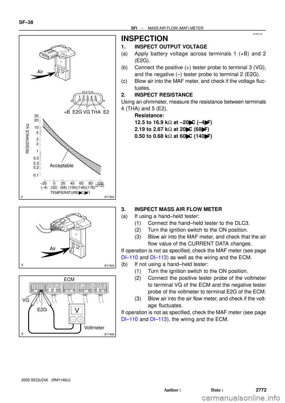
1. INSPECT OUTPUT VOLTAGE
(a) Apply battery voltage across terminals 1 (+B) and 2
(E2G).
(b) Connect the positive (+) tester probe to terminal 3 (VG),
and the negative (±) tester probe to terminal 2 (E2G).
(c) Blow air into the MAF meter, and check if the voltage fluc-
tuates.
2. INSPECT RESISTANCE
Using an ohmmeter, measure the resistance between terminals
4 (THA) and 5 (E2).
Resistance:
12.5 to 16.9 kW at ±20�C (±4�F)
2.19 to 2.67 kW at 20�C (68�F)
0.50 to 0.68 kW at 60�C (140�F)
3. INSPECT MASS AIR FLOW METER
(a) If using a hand±held tester:
(1) Connect the hand±held tester to the DLC3.
(2) Turn the ignition switch to the ON position.
(3) Blow air into the MAF meter, and check that the air
flow value of the CURRENT DATA changes.
If operation is not as specified, check the MAF meter (see page
DI±110 and DI±113) as well as the wiring and the ECM.
(b) If not using a hand±held tester:
(1) Turn the ignition switch to the ON position.
(2) Connect the positive tester probe of the voltmeter
to terminal VG of the ECM and the negative tester
probe of the voltmeter to terminal E2G of the ECM.
(3) Blow air into the air flow meter, and check if the volt-
age fluctuates.
If operation is not as specified, check the MAF meter (see page
DI±110 and DI±113), the wiring and the ECM.
Page 2781 of 4323

B17467
SF1XJ±01
D13872
Hand±Held Tester
DLC3
CAN VIM
± SFITHROTTLE BODY
SF±39
2773 Author�: Date�:
2005 SEQUOIA (RM1146U)
THROTTLE BODY
ON±VEHICLE INSPECTION
1. REMOVE THROTTLE BODY COVER
2. INSPECT SYSTEM OPERATION
(a) Inspect the throttle control motor for operating sound.
(1) Turn the ignition switch ON.
(2) When depressing the accelerator pedal, check the
running sound of the motor. Also, check that there
is no friction sound.
If operation is not as specified, check the throttle control motor
(see step 3), wiring and ECM.
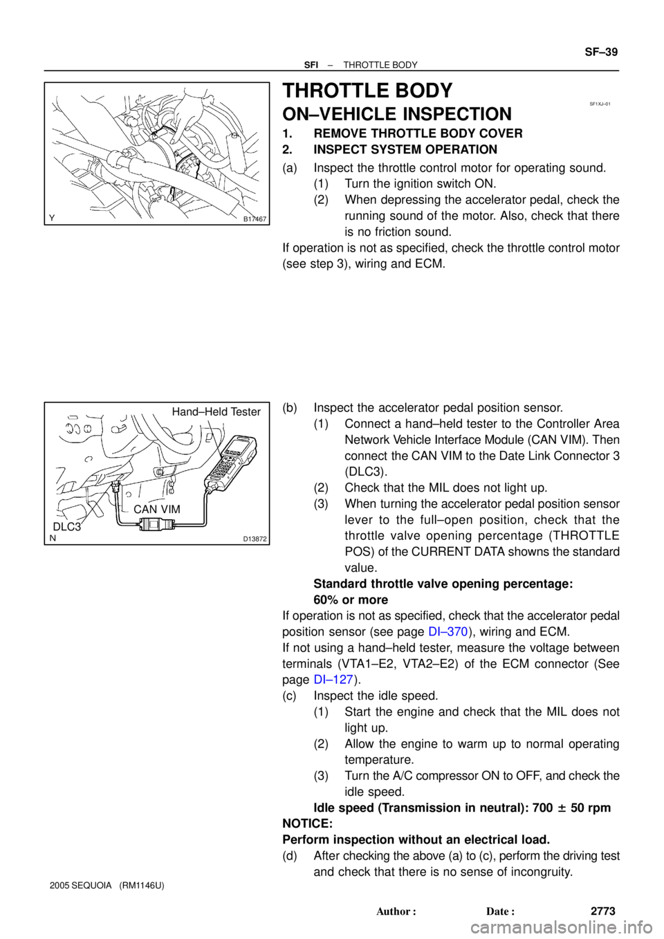
(b) Inspect the accelerator pedal position sensor.
(1) Connect a hand±held tester to the Controller Area
Network Vehicle Interface Module (CAN VIM). Then
connect the CAN VIM to the Date Link Connector 3
(DLC3).
(2) Check that the MIL does not light up.
(3) When turning the accelerator pedal position sensor
lever to the full±open position, check that the
throttle valve opening percentage (THROTTLE
POS) of the CURRENT DATA showns the standard
value.
Standard throttle valve opening percentage:
60% or more
If operation is not as specified, check that the accelerator pedal
position sensor (see page DI±370), wiring and ECM.
If not using a hand±held tester, measure the voltage between
terminals (VTA1±E2, VTA2±E2) of the ECM connector (See
page DI±127).
(c) Inspect the idle speed.
(1) Start the engine and check that the MIL does not
light up.
(2) Allow the engine to warm up to normal operating
temperature.
(3) Turn the A/C compressor ON to OFF, and check the
idle speed.
Idle speed (Transmission in neutral): 700 ± 50 rpm
NOTICE:
Perform inspection without an electrical load.
(d) After checking the above (a) to (c), perform the driving test
and check that there is no sense of incongruity.
Page 2782 of 4323
B17499
M±
M+
Ohmmeter SF±40
± SFITHROTTLE BODY
2774 Author�: Date�:
2005 SEQUOIA (RM1146U)
3. INSPECT THROTTLE CONTROL MOTOR
(a) Disconnect the throttle control motor connector.
(b) Using an ohmmeter, measure the motor resistance be-
tween terminals M+ and M±.
Motor resistance: 0.3 to 100 W at 20°C (68°F)
If the resistance is not as specified, replace the throttle body as-
sembly (see page SF±42).
(c) Reconnect the throttle control motor connector.
4. INSPECT THROTTLE POSITION SENSOR
(See page DI±127)
If necessary, replace the throttle body assembly (see page
SF±42).
5. REINSTALL THROTTLE BODY COVER
Page 2785 of 4323
B17469
SF0P7±16
B17470
± SFITHROTTLE BODY
SF±43
2777 Author�: Date�:
2005 SEQUOIA (RM1146U)
INSTALLATION
1. INSTALL THROTTLE BODY
(a) Install the throttle body with the nut and 3 bolts.
Torque: 14 N´m (143 kgf´cm, 10 ft´lbf)
(b) Connect the 2 water bypass hoses to the throttle body.
(c) Connect the throttle control connector.
2. INSTALL INTAKE AIR CONNECTOR
3. FILL WITH ENGINE COOLANT (See page CO±2)
4. START ENGINE AND CHECK FOR ENGINE COOLANT
LEAKS
5. INSTALL THROTTLE BODY COVER
Page 2790 of 4323
SF1XL±01
SF±48
± SFICAMSHAFT TIMING OIL CONTROL VALVE
2782 Author�: Date�:
2005 SEQUOIA (RM1146U)
INSTALLATION
Installation is in the reverse order of removal. (See page SF±46)
Page 2795 of 4323
SF1XN±01
B17510
± SFIACOUSTIC CONTROL INDUCTION SYSTEM (ACIS)
SF±53
2787 Author�: Date�:
2005 SEQUOIA (RM1146U)
REMOVAL
1. REMOVE THROTTLE BODY COVER
2. REMOVE INTAKE MANIFOLD ASSEMBLY
(See page EM±36)
3. REMOVE VSV FOR ACIS
(a) Remove the 2 vacuum hoses from the VSV.
(b) Remove the bolt and VSV from the intake manifold.
Page 2797 of 4323
SF1XP±01
B17510
± SFIACOUSTIC CONTROL INDUCTION SYSTEM (ACIS)
SF±55
2789 Author�: Date�:
2005 SEQUOIA (RM1146U)
INSTALLATION
1. INSTALL VSV FOR ACIS
(a) Install the VSV to the intake manifold with the bolt.
Torque: 7.5 N´m (76 kgf´cm, 66 in.´lbf)
(b) Connect the 2 vacuum hoses to the VSV.
2. INSTALL INTAKE MANIFOLD ASSEMBLY
(See page EM±60)
3. INSTALL THROTTLE BODY COVER