Page 2687 of 4323
A04847
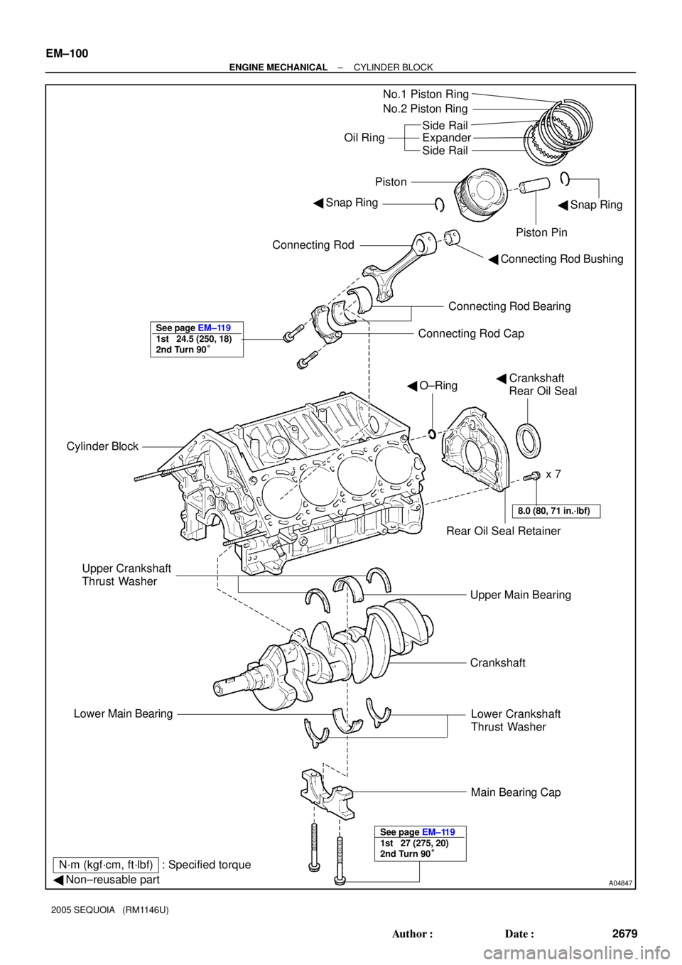
No.1 Piston Ring
No.2 Piston Ring
Oil RingSide Rail
Expander
Side Rail
Connecting Rod
Connecting Rod Bearing
Connecting Rod Cap
Cylinder Block� Snap Ring
Piston Pin
� Crankshaft
Rear Oil Seal � O±Ring
Rear Oil Seal Retainer
Upper Main Bearing� Snap Ring Piston
Upper Crankshaft
Thrust Washer
Lower Main Bearing
Lower Crankshaft
Thrust Washer
Main Bearing Cap
� Non±reusable partx 7
Crankshaft
N´m (kgf´cm, ft´lbf) : Specified torque� Connecting Rod Bushing
See page EM±119
1st 24.5 (250, 18)
2nd Turn 90°
See page EM±119
1st 27 (275, 20)
2nd Turn 90°
8.0 (80, 71 in.´lbf)
EM±100
± ENGINE MECHANICALCYLINDER BLOCK
2679 Author�: Date�:
2005 SEQUOIA (RM1146U)
Page 2688 of 4323

DISASSEMBLY
1. INSTALL ENGINE TO ENGINE STAND
2. REMOVE")
EM122±05
A05112
Pull
Wire
Clamp
O±Ring
A08472
LH Side
± ENGINE MECHANICALCYLINDER BLOCK
EM±101
2680 Author�: Date�:
2005 SEQUOIA (RM1146U)
DISASSEMBLY
1. INSTALL ENGINE TO ENGINE STAND
2. REMOVE TIMING BELT AND PULLEYS
(See page EM±16)
3. REMOVE CYLINDER HEAD (See page EM±36)
4. REMOVE WATER BYPASS PIPE
(a) Disconnect the wire clamp (for knock sensor 1, 2) from
bracket of the water bypass pipe.
(b) Remove the bolt.
(c) Pull out the water bypass pipe from the water pump.
(d) Remove the O±ring from the water bypass pipe.
5. REMOVE STARTER (See page ST±5)
6. REMOVE KNOCK SENSORS (See page SF±66)
7. REMOVE VVT SENSORS (See page SF±77)
8. DISCONNECT ENGINE WIRE FROM LH SIDE OF CYL-
INDER BLOCK
(a) Remove the 2 bolts and engine wire cover from the LH
side of the cylinder block.
(b) Remove the 2 bolts, disconnect the brackets on the en-
gine wire from the cylinder block and engine mounting
bracket.
9. REMOVE OIL COOLER PIPE BRACKET FOR A/T
Remove the bolt and bracket.
10. REMOVE ENGINE MOUNTING BRACKETS
Remove the 4 bolts and mounting bracket. Remove the 2
mounting brackets.
11. REMOVE WATER PUMP (See page CO±6)
12. REMOVE NO.2 OIL PAN (See page LU±8)
13. REMOVE OIL PAN BAFFLE PLATE
14. REMOVE NO.1 OIL PAN (See page LU±8)
15. REMOVE OIL STRAINER
16. REMOVE OIL PUMP (See page LU±8)
17. REMOVE ENGINE COOLANT DRAIN UNIONS
Remove the 2 drain unions.
Page 2690 of 4323

A05102
Plastigage
A05101
A05103
A05852
A05087A05853A05175
Number
Mark
Number
Mark
Number
Mark No.1
No.2No.3No.4
Connecting rod cap
Crankshaft
Use bearingNumber mark1
2
34 76 1
21
1 2
1
32
23
12
33
24
13
344
23
5
EXAMPLE:
Connecting rod cap º3º + Crankshaft º1º
= Total number 4 (Use bearing º4º)
± ENGINE MECHANICALCYLINDER BLOCK
EM±103
2682 Author�: Date�:
2005 SEQUOIA (RM1146U)
(f) Lay a strip of Plastigage across the crank pin.
(g) Install the connecting rod cap with the 2 bolts.
(see page EM±119)
NOTICE:
Do not turn the crankshaft.
(h) Remove the 2 bolts, connecting rod cap and lower bear-
ing. (See procedure (b) and (c) above)
(i) Measure the Plastigage at its widest point.
Standard oil clearance:
0.021 to 0.047 mm (0.0008 to 0.0019 in.)
Maximum oil clearance: 0.059 mm (0.0023 in.)
If the oil clearance is greater than maximum, replace the bear-
ings. If necessary, replace the crankshaft.
HINT:
If using a standard bearing, replace it with one having the same
number. If the number of the bearing cannot be determined, se-
lect the correct bearing by adding together the numbers im-
printed on the connecting rod cap and crankshaft, then select-
ing the bearing with the same number as the total. There are 6
sizes of standard bearings, marked º2º, º3º, º4º, º5º, º6º and º7º.
Page 2692 of 4323

(b) Using 2 screwdrivers, pry out the main bearing cap, and
remove the 5")
A05093
A05097
Plastigage
A05095
A05098
± ENGINE MECHANICALCYLINDER BLOCK
EM±105
2684 Author�: Date�:
2005 SEQUOIA (RM1146U)
(b) Using 2 screwdrivers, pry out the main bearing cap, and
remove the 5 main bearing caps, 5 lower bearings and 2
lower thrust washers (No.3 main bearing cap only).
NOTICE:
Be careful not to damage the cylinder block.
HINT:
�Keep the lower bearing and main bearing cap together.
�Arrange the main bearing caps and lower thrust washers
in correct order.
(c) Lift out the crankshaft.
HINT:
Keep the upper bearings and upper thrust washers together
with the cylinder block.
(d) Clean each main journal and bearing.
(e) Check each main journal and bearing for peelings and
scratches.
If the journal or bearing is damaged, replace the bearings. If
necessary, replace the crankshaft.
(f) Place the crankshaft on the cylinder block.
(g) Lay a strip of Plastigage across each journal.
(h) Install the main bearing caps. (See page EM±119)
NOTICE:
Do not turn the crankshaft.
(i) Remove the main bearing caps.
(See procedure (a) and (b) above)
(j) Measure the Plastigage at its widest point.
Standard clearance:
No.1, No.5
0.028 to 0.046 mm (0.0011 to 0.0018 in.)
Others
0.040 to 0.058 mm (0.0016 to 0.0023 in.)
Maximum clearance: 0.065 mm (0.0026 in.)
If the oil clearance is greater than maximum, replace the bear-
ings. If necessary, replace the crankshaft.
Page 2696 of 4323
EM0EB±17
A04849
A04850A04210A04212A05178
Cylinder Block Side
Main Bearing Cap Side
A04853
± ENGINE MECHANICALCYLINDER BLOCK
EM±109
2688 Author�: Date�:
2005 SEQUOIA (RM1146U)
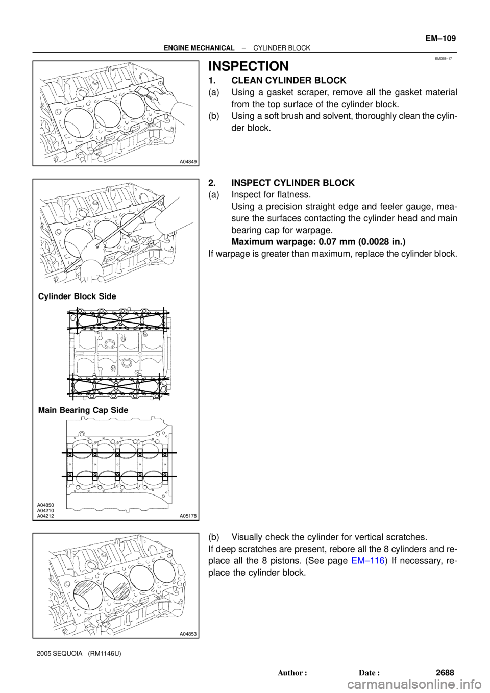
INSPECTION
1. CLEAN CYLINDER BLOCK
(a) Using a gasket scraper, remove all the gasket material
from the top surface of the cylinder block.
(b) Using a soft brush and solvent, thoroughly clean the cylin-
der block.
2. INSPECT CYLINDER BLOCK
(a) Inspect for flatness.
Using a precision straight edge and feeler gauge, mea-
sure the surfaces contacting the cylinder head and main
bearing cap for warpage.
Maximum warpage: 0.07 mm (0.0028 in.)
If warpage is greater than maximum, replace the cylinder block.
(b) Visually check the cylinder for vertical scratches.
If deep scratches are present, rebore all the 8 cylinders and re-
place all the 8 pistons. (See page EM±116) If necessary, re-
place the cylinder block.
Page 2697 of 4323

10 mm
(0.39 in.) Front
1
2
1
A04852
Ridge
Reamer
A05")
A04211Mark 1, 2 or 3 Front
No.2 No.4 No.6 No.8
No.1 No.3 No.5 No.7
:
A04262A04851A05181
1
2
B
C
AThrust
Direction
Axial
Direction
10 mm
(0.39 in.)
10 mm
(0.39 in.) Front
1
2
1
A04852
Ridge
Reamer
A0513850 ± 64 mm (1.97 ± 2.52 in.) EM±110
± ENGINE MECHANICALCYLINDER BLOCK
2689 Author�: Date�:
2005 SEQUOIA (RM1146U)
(c) Inspect the cylinder bore diameter.
HINT:
There are 3 sizes of the standard cylinder bore diameter,
marked º1º, º2º and º3º accordingly. The mark is stamped on the
top of the cylinder block.
Using a cylinder gauge, measure the cylinder bore diame-
ter at positions A, B and C in the thrust and axial direc-
tions.
Standard diameter:
STD Mark º1º94.002 to 94.010 mm (3.7009 to 3.7012 in.)STD Mark 1
Mark º2º
94.002 to 94.010 mm (3.7009 to 3.7012 in.)
94.010 to 94.023 mm (3.7012 to 3.7017 in.)Mark 2
Mark º3º
94.010 to 94.023 mm (3.7012 to 3.7017 in.)
94.023 to 94.031 mm (3.7017 to 3.7020 in.)
Maximum diameter:
STD94.231 mm (3.7099 in.)
O/S 0.5094.731 mm (3.7296 in.)
If the diameter is greater than maximum, rebore all the 8 cylin-
ders and replace all the 8 pistons. (See page EM±116) If neces-
sary, replace the cylinder block.
(d) Remove the cylinder ridge.
If the wear is less than 0.2 mm (0.008 in.), using a ridge reamer,
grind the top of the cylinder.
(e) Using vernier calipers, measure the thread outside diam-
eter of the main bearing cap bolt.
Standard diameter:
10.760 to 10.970 mm (0.4236 to 0.4319 in.)
Minimum diameter: 10.40 mm (0.4094 in.)
If the diameter is less than minimum, replace the cap bolt.
Page 2699 of 4323

Front
Mark
(2 Cavities)
A04880
EM±112
± EN")
A23368
Cylinder Block
Front
No.2 No.4 No.6
No.8
No.1
No.5 No.7
RH Piston
No.3
:
LH PistonMark 1, 2 or 3
Mark 1, 2 or 3 Mark 1, 2 or 3
Front
Mark
(1 Cavity)
Front
Mark
(2 Cavities)
A04880
EM±112
± ENGINE MECHANICALCYLINDER BLOCK
2691 Author�: Date�:
2005 SEQUOIA (RM1146U)
(3) Subtract the piston diameter measurement from the
cylinder bore diameter measurement.
Standard oil clearance:
0.030 to 0.071 mm (0.0012 to 0.0028 in.)
Maximum oil clearance: 0.13 mm (0.0051 in.)
If the oil clearance is greater than maximum, replace all the 8
pistons and rebore all the 8 cylinders. (See page EM±116) If
necessary, replace the cylinder block.
HINT
Use a new cylinder block:
�Use a piston with the same number mark as the cylinder
diameter number marked on the cylinder block.
�The shape of the piston differs for the LH and RH banks.
The LH piston is marked with 1 cavity and º2º, the RH pis-
ton with 2 cavities and º2º.
(b) Inspect the piston ring groove clearance.
Using a feeler gauge, measure the clearance between
the new piston ring and the wall of the ring groove.
Ring groove clearance:
No.10.030 to 0.080 mm (0.0012 to 0.0031 in.)
No.20.020 to 0.060 mm (0.0008 to 0.0024 in.)
If the clearance is not as specified, replace the piston.
Page 2700 of 4323

(c) Inspect the piston ring end gap.
(1) Insert the piston ring into t")
A04872
105 mm
EM7639
A04048
60°C
Z14454
± ENGINE MECHANICALCYLINDER BLOCK
EM±113
2692 Author�: Date�:
2005 SEQUOIA (RM1146U)
(c) Inspect the piston ring end gap.
(1) Insert the piston ring into the cylinder bore.
(2) Using a piston, push the piston ring a little to the bot-
tom of the ring travel, 105 mm (4.13 in.) from the top
of the cylinder block.
(3) Using a feeler gauge, measure the end gap.
Standard end gap:
No.10.300 to 0.400 mm (0.0118 to 0.0157 in.)
No.20.400 to 0.550 mm (0.0157 to 0.0217 in.)
Oil (Side rail)0.130 to 0.380 mm (0.0051 to 0.0150 in.)
Maximum end gap:
No.11.10 mm (0.0433 in.)
No.21.30 mm (0.0512 in.)
Oil (Side rail)0.90 mm (0.0354 in.)
If the end gap is greater than maximum, replace the piston ring.
If the end gap is greater than maximum, even with a new piston
ring, rebore all the 8 cylinders (See page EM±116) or replace
the cylinder block.
(d) Inspect the piston pin fit.
At 60°C (140°F), you should be able to push the piston
pin into the piston pin hole with your thumb.
(e) Using a rod aligner and feeler gauge, check the connect-
ing rod alignment.
(1) Check for bend.
Maximum bend:
0.05 mm (0.0020 in.) per 100 mm (3.94 in.)
If bend is greater than maximum, replace the connecting rod as-
sembly.