Page 2604 of 4323
A04330
A04455
A23305
A23306
SST
± ENGINE MECHANICALTIMING BELT
EM±17
2596 Author�: Date�:
2005 SEQUOIA (RM1146U)
(g) Remove the LH No.3 timing belt cover.
(h) Remove the bolt, nut and oil cooler pipe.
11. REMOVE NO.2 TIMING BELT COVER
Remove the 2 bolts and No.2 timing belt cover.
12. DISCONNECT A/C COMPRESSOR FROM ENGINE
(See page EM±79)
13. REMOVE FAN BRACKET
Remove the 2 bolts, 2 nuts and fan bracket.
14. IF RE±USING TIMING BELT, CHECK INSTALLATION
MARKS ON TIMING BELT
Check that there are 3 installation marks on the timing belt by
turning the crankshaft pulley as shown in the illustration.
HINT:
If the installation marks have disappeared, place a new installa-
tion mark on the timing belt before removing each part.
15. LOOSEN CRANKSHAFT PULLEY BOLT
Using SST, loosen the pulley bolt.
SST 09213±70011 (90105±08076), 09330±00021
Page 2606 of 4323

�When replacing the timing belt tensioner only:
To avoid meshi")
A23310
String
A04339
A23311
Slightly Turn
A23312
SST
± ENGINE MECHANICALTIMING BELT
EM±19
2598 Author�: Date�:
2005 SEQUOIA (RM1146U)
�When replacing the timing belt tensioner only:
To avoid meshing of the timing pulley and timing belt, se-
cure one of them with string. And place matchmarks on
the timing belt and RH camshaft timing pulley.
Alternately loosen the 2 bolts, and remove them, the belt ten-
sioner and dust boot.
18. DISCONNECT TIMING BELT FROM CAMSHAFT TIM-
ING PULLEYS
(a) Hold the camshaft timing pulley with SST, and loosen the
tension spring between the LH and RH camshaft timing
pulleys by slightly turning the LH camshaft timing pulley
clockwise.
SST 09960±10010 (09962±01000, 09963±01000)
HINT:
Set the SST so that the claw comes in contact with the camshaft
timing pulley bolt, and tighten the lock nut of the SST.
(b) Disconnect the timing belt from the camshaft timing pul-
leys.
19. REMOVE CAMSHAFT TIMING PULLEYS
(a) Hold the camshaft timing pulley with SST, loosen the 4
bolts of the timing pulley.
SST 09960±10010 (09962±01000, 09963±01000)
(b) Remove the 2 timing pulleys.
20. REMOVE GENERATOR (See page CH±7)
21. REMOVE DRIVE BELT TENSIONER
Remove the bolt, 2 nuts and belt tensioner.
Page 2609 of 4323
P20634
P20635
Protrusion EM±22
± ENGINE MECHANICALTIMING BELT
2601 Author�: Date�:
2005 SEQUOIA (RM1146U)
(b) Hold the tensioner with both hands and push the push rod
strongly as shown to check that it doesn't move.
If the push rod moves, replace the tensioner.
NOTICE:
Never hold the tensioner push rod facing downward.
(c) Measure the protrusion of the push rod from the housing
end.
Protrusion: 10.5 to 11.5 mm (0.413 to 0.453 in.)
If the protrusion is not as specified, replace the tensioner.
4. INSPECT WATER PUMP (See page CO±7)
Page 2611 of 4323

5. INSTALL TIMING BELT GUIDE
Install the belt guide with the cup side facing ou")
A04448
A23314
SST
A08660
A23315
SST
EM±24
± ENGINE MECHANICALTIMING BELT
2603 Author�: Date�:
2005 SEQUOIA (RM1146U)
5. INSTALL TIMING BELT GUIDE
Install the belt guide with the cup side facing outward.
6. INSTALL NO.1 TIMING BELT COVER
Install the timing belt cover with the 4 bolts.
7. INSTALL CRANKSHAFT PULLEY
(a) Align the pulley set key with the key groove of the crank-
shaft pulley.
(b) Using SST and a hammer, tap in the crankshaft pulley.
SST 09223±46011
8. INSTALL DRIVE BELT TENSIONER
Install the belt tensioner with the bolt and 2 nuts.
Torque: 26 N´m (265 kgf´cm, 19 ft´lbf)
HINT:
Use a bolt of 106 mm (4.18 in.) in length.
9. INSTALL GENERATOR (See page CH±16)
10. CHECK CRANKSHAFT PULLEY POSITION
Check that the timing mark of the crankshaft pulley is aligned
with timing mark º0º of the No.1 timing belt cover.
11. INSTALL, LH CAMSHAFT TIMING PULLEY
(a) Align the camshaft knock pin with the knock pin groove of
the timing pulley, and slide the timing pulley.
(b) Temporarily install the 4 bolts of the camshaft timing
pulley.
(c) Hold the camshaft timing pulley with SST, and tighten the
pulley bolt.
SST 09960±10010 (09962±01000, 09963±01000)
Torque: 8.1 N´m (83 kgf´cm, 72 in.´lbf)
Page 2614 of 4323
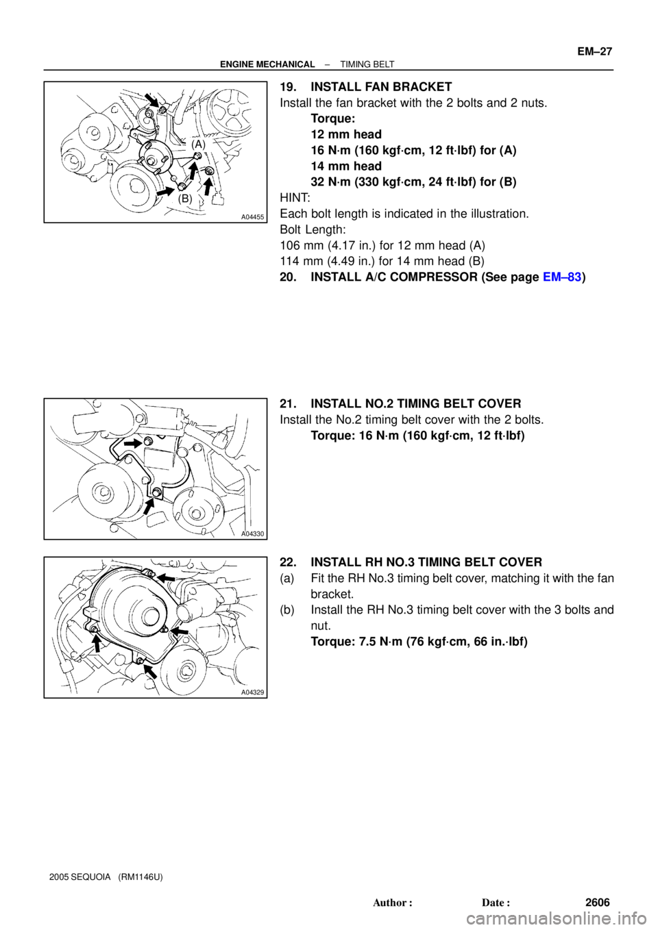
A04455
(A)
(B)
A04330
A04329
± ENGINE MECHANICALTIMING BELT
EM±27
2606 Author�: Date�:
2005 SEQUOIA (RM1146U)
19. INSTALL FAN BRACKET
Install the fan bracket with the 2 bolts and 2 nuts.
Torque:
12 mm head
16 N´m (160 kgf´cm, 12 ft´lbf) for (A)
14 mm head
32 N´m (330 kgf´cm, 24 ft´lbf) for (B)
HINT:
Each bolt length is indicated in the illustration.
Bolt Length:
106 mm (4.17 in.) for 12 mm head (A)
114 mm (4.49 in.) for 14 mm head (B)
20. INSTALL A/C COMPRESSOR (See page EM±83)
21. INSTALL NO.2 TIMING BELT COVER
Install the No.2 timing belt cover with the 2 bolts.
Torque: 16 N´m (160 kgf´cm, 12 ft´lbf)
22. INSTALL RH NO.3 TIMING BELT COVER
(a) Fit the RH No.3 timing belt cover, matching it with the fan
bracket.
(b) Install the RH No.3 timing belt cover with the 3 bolts and
nut.
Torque: 7.5 N´m (76 kgf´cm, 66 in.´lbf)
Page 2615 of 4323

23. INSTALL LH NO.3 TIMING BELT COVER
(a) Install the oil cooler pipe with the bolt and nut.
(b) Run")
A04331
A08934
EM±28
± ENGINE MECHANICALTIMING BELT
2607 Author�: Date�:
2005 SEQUOIA (RM1146U)
23. INSTALL LH NO.3 TIMING BELT COVER
(a) Install the oil cooler pipe with the bolt and nut.
(b) Run the camshaft position sensor wire through the LH
No.3 timing belt cover hole.
(c) Fit the LH No.3 timing belt cover, matching it with the fan
bracket.
(d) Install the LH No.3 timing belt cover with the 4 bolts and
nut.
Torque: 7.5 N´m (76 kgf´cm, 66 in.´lbf)
(e) Install the wire grommet to the LH No.3 timing belt cover.
(f) Install the camshaft position sensor connector to the con-
nector bracket.
(g) Connect the camshaft position sensor connector.
(h) Install the sensor wire to the wire clamp on the LH No.3
timing belt cover.
(i) Install the engine wire to the 2 wire clamps on the LH No.3
timing belt cover.
24. INSTALL DRIVE BELT IDLER PULLEY
Install the idler pulley and cover plate with the bolt.
Torque: 39 N´m (400 kgf´cm, 29 ft´lbf)
25. INSTALL PS PUMP
Install the PS pump with the 3 bolts.
Torque: 17 N´m (175 kgf´cm, 13 ft´lbf)
26. INSTALL FAN PULLEY, FAN, FLUID COUPLING
AND DRIVE BELT
(a) Temporarily install the fan pulley, the fan, fluid coupling
assembly with the 4 nuts.
(b) Install the drive belt. (See page CH±16)
(c) Tighten the 4 nuts holding the fluid coupling to the fan
bracket.
Torque: 29 N´m (296kgf´cm, 21 ft´lbf)
27. INTAKE AIR CONNECTOR ASSEMBLY
28. INSTALL THROTTLE BODY COVER
29. INSTALL RADIATOR ASSEMBLY (See page CO±18)
30. FILL WITH ENGINE COOLANT
31. START ENGINE AND CHECK FOR LEAKS
32. RECHECK ENGINE COOLANT LEVEL
33. INSTALL ENGINE UNDER COVER
Page 2621 of 4323
 : Specified torque Camshaft Timing
Oil Control Valve
(Bank 2) Connector
RH Cylinder
Head Cover
Engine
Wire
Clamp
Bracket� Spark Plug Tube
Gasket")
A23322� Non±reusable part
N´m (kgf´cm, ft´lbf) : Specified torque Camshaft Timing
Oil Control Valve
(Bank 2) Connector
RH Cylinder
Head Cover
Engine
Wire
Clamp
Bracket� Spark Plug Tube
Gasket
Seal
Washer LH Cylinder
Head Cover
RH Intake
Camshaft
(with Timing
Tube)
Semi±circular Plug
Ground Strap
Ground WireEngine Wire
Clamp
x 9
Camshaft
Timing Oil
Control Valve
(Bank 1)
Camshaft Timing
Oil Control Valve
(Bank 2)
Front
Bearing Cap
Spark PlugGasket
Oil
Feed
Pipe
� Seal
Washer
Ground Wire
Camshaft Bearing Cap
16 (160, 12)� O±Ring
LH Exhaust
Camshaft
Camshaft
Housing Plug
Semi±circular
Plug
Strainer
� O±Ring
Gasket
�
LH Intake Camshaft
(with Timing Tube)
RH Exhaust
Camshaft
Camshaft
Housing
Plug
Engine Wire
Bracket
� LH Cylinder Head GasketLH Cylinder Head and
Exhaust Manifold Assembly
Air±fuel Ratio Sensor
(Bank 1 Sensor 1) Connector
RH Cylinder
Head Gasket
Engine
Wire
7.5 (76, 66 in.´lbf)
7.5 (76, 66 in.´lbf)
Seal
Washerx 9
x 10
�Camshaft Timing
Oil Control Valve
(Bank 1) Connector
Air±fuel Ratio Sensor
(Bank 2 Sensor 1)
Connector
Strainer
1st 40 (408, 30)
2nd Turn 90°
3rd
Turn 90° See page EM±60
Front
Bearing Cap
6.0 (600, 53 in.´lbf)
6.0 (600, 53 in.´lbf)
EM±34
± ENGINE MECHANICALCYLINDER HEAD
2613 Author�: Date�:
2005 SEQUOIA (RM1146U)
Page 2623 of 4323

REMOVAL
1. DRAIN ENGINE COOLANT
2. REMOVE THROTTLE BODY COVER
3. DISCONNECT TIMING BELT FROM CAM")
EM1X0±01
A02844
EM±36
± ENGINE MECHANICALCYLINDER HEAD
2615 Author�: Date�:
2005 SEQUOIA (RM1146U)
REMOVAL
1. DRAIN ENGINE COOLANT
2. REMOVE THROTTLE BODY COVER
3. DISCONNECT TIMING BELT FROM CAMSHAFT TIM-
ING PULLEYS (See page EM±16)
NOTICE:
�Be careful not to drop anything inside the timing belt
cover.
�Do not allow the belt to come into correct with oil, wa-
ter or dust.
4. REMOVE CAMSHAFT TIMING PULLEYS
(See page EM±16)
5. REMOVE CAMSHAFT POSITION SENSOR
(See page IG±8)
6. DISCONNECT PS PUMP FROM ENGINE
(See page EM±79)
7. REMOVE FRONT EXHAUST PIPE (See page EM±126)
8. REMOVE OIL DIPSTICK AND GUIDE FOR A/T
9. REMOVE IGNITION COILS (See page IG±5)
10. REMOVE TIMING BELT REAR PLATES
(a) Remove the 3 bolts, stud bolt and RH No.1 timing belt rear
plates.
(b) Disconnect the wire clamp from the LH timing belt rear
plate.
(c) Remove the 3 bolts, stud bolt and LH No.1 timing belt rear
plates.
11. DISCONNECT FUEL INLET HOSE (See page SF±27)
AND FUEL RETURN HOSE
12. DISCONNECT CONNECTORS FROM INTAKE MAN-
IFOLD
(a) Disconnect the throttle control connector.
(b) Disconnect the VSV connector for EVAP.
(c) Disconnect the 8 injector connectors.
(d) Disconnect the ECT sensor connector.
(e) Disconnect the 2 VSV connectors for the air injection sys-
tem.
(f) Disconnect the 8 ignition coil connectors.
(g) Disconnect the 2 air fuel ratio sensor connectors.