Page 2585 of 4323
± DIAGNOSTICSAIR CONDITIONING SYSTEM
DI±2383
2577 Author�: Date�:
2005 SEQUOIA (RM1146U)
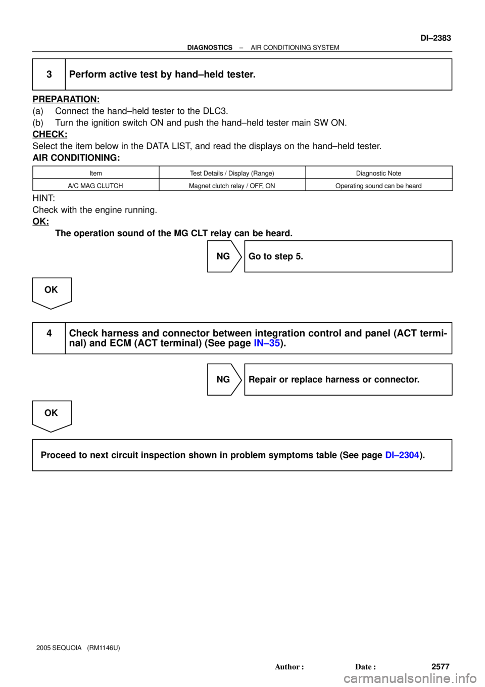
3 Perform active test by hand±held tester.
PREPARATION:
(a) Connect the hand±held tester to the DLC3.
(b) Turn the ignition switch ON and push the hand±held tester main SW ON.
CHECK:
Select the item below in the DATA LIST, and read the displays on the hand±held tester.
AIR CONDITIONING:
ItemTest Details / Display (Range)Diagnostic Note
A/C MAG CLUTCHMagnet clutch relay / OFF, ONOperating sound can be heard
HINT:
Check with the engine running.
OK:
The operation sound of the MG CLT relay can be heard.
NG Go to step 5.
OK
4 Check harness and connector between integration control and panel (ACT termi-
nal) and ECM (ACT terminal) (See page IN±35).
NG Repair or replace harness or connector.
OK
Proceed to next circuit inspection shown in problem symptoms table (See page DI±2304).
Page 2586 of 4323
Z18060
15 2
3
12 3 5
I21361
3
DI±2384
± DIAGNOSTICSAIR CONDITIONING SYSTEM
2578 Author�: Date�:
2005 SEQUOIA (RM1146U)
5 Check magnetic clutch relay.
PREPARATION:
Remove the magnetic clutch relay from the engine room J/B.
CHECK:
Measure the resistance according to the value(s) in the table
below.
OK:
Tester connectionConditionSpecified condition
3 ± 5Always10 kW or higher
3 ± 5
Voltage is applied
between terminals
1 and 2Below 1W (Battery
voltage is applied between
terminals 1 and 2)
NG Replace magnetic clutch relay.
OK
6 Check A/C magnetic clutch.
PREPARATION:
Disconnect the magnetic clutch connector.
CHECK:
Connect the positive (+) battery lead to the magnetic clutch con-
nector terminal 3.
OK:
Magnetic clutch is energized.
NG Replace A/C magnetic clutch.
OK
7 Check harness and connector between integration control and panel (MGC ter-
minal) and body ground (See page IN±35).
NG Repair or replace harness or connector.
OK
Replace integration control and panel.
Page 2587 of 4323
I28847
AC1 Integration Control and Panel
I22
± DIAGNOSTICSAIR CONDITIONING SYSTEM
DI±2385
2579 Author�: Date�:
2005 SEQUOIA (RM1146U)
8 Check harness and connector between integration control and panel (AC1 termi-
nal) and ECM (AC1 terminal) (See page IN±35).
NG Repair or replace harness or connector.
OK
9 Check voltage between terminal AC1 of integration control and panel connector
and body ground.
PREPARATION:
(a) Disconnect the connector from the ECM.
(b) Remove the integration control and panel with the con-
nectors still connected.
(c) Start the engine and push the AUTO switch.
CHECK:
Measure the voltage between terminal AC1 of the integration
control and panel connector and body ground when the mag-
netic clutch is turned ON and OFF by the A/C switch.
OK:
Switch operationTester connectionSpecified condition
ONAC1 ± Body ground1.3 to 2.6 V
OFFAC1 ± Body ground3.7 to 4.5 V
NG Replace integration control and panel.
OK
Replace ECM (See page SF±80).
Page 2589 of 4323

5. IMMEDIATELY CHECK CO/HC CONCENTRATION AT
IDLE AND/OR 2,500 RPM
HINT:
When performing the 2 mode (2,500 rpm and idle) te")
EM±2
± ENGINE MECHANICALCO/HC
2581 Author�: Date�:
2005 SEQUOIA (RM1146U)
5. IMMEDIATELY CHECK CO/HC CONCENTRATION AT
IDLE AND/OR 2,500 RPM
HINT:
When performing the 2 mode (2,500 rpm and idle) test, follow
the measurement orders are prescribed by the applicable local
regulations.
If the CO/HC concentration does not comply with regulations,
perform troubleshooting in the order given below.
(a) Check the air±fuel ratio sensors and heated oxygen sen-
sors operation.(See page DI±88 and DI±93)
(b) See the table below for possible causes, and then inspect
and correct the applicable causes if necessary.
COHCProblemsCauses
NormalHighRough idle7. Faulty ignitions:
�Incorrect timing
�Fouled, shorted or improperly gapped plugs
8. Incorrect valve clearance
9. Leaky intake and exhaust valves
10.Leaky cylinders
LowHighRough idle
(fluctuating HC reading)1. Vacuum leaks:
�PCV hoses
�Intake manifold
�Throttle body
�Brake booster line
2. Lean mixture causing misfire
HighHighRough idle
(Black smoke from exhaust)1. Restricted air filter
2. Faulty SFI systems:
�Faulty pressure regulator
�Defective ECT sensor
�Faulty ECM
�Faulty injectors
�Faulty throttle position sensor
�Faulty MAF meter
Page 2590 of 4323

COMPRESSION
INSPECTION
HINT:
If there is lack of power, excessive oil consumption")
EM0KR±10
A04458
Compression
Gauge
± ENGINE MECHANICALCOMPRESSION
EM±3
2582 Author�: Date�:
2005 SEQUOIA (RM1146U)
COMPRESSION
INSPECTION
HINT:
If there is lack of power, excessive oil consumption or poor fuel
economy, measure the compression pressure.
1. WARM UP AND STOP ENGINE
Allow the engine to warm up to normal operating temperature.
2. REMOVE SPARK PLUGS (See page IG±1)
3. CHECK CYLINDER COMPRESSION PRESSURE
(a) Insert a compression gauge into the spark plug hole.
(b) Fully open the throttle.
(c) While cranking the engine, measure the compression
pressure.
HINT:
Always use a fully charged battery to obtain engine speed of
250 rpm or more.
(d) Repeat steps (a) through (c) for each cylinder.
NOTICE:
This measurement must be done in as short a time as pos-
sible.
Compression pressure:
1,373 kPa (14.0 kgf/cm
2, 199 psi) or more
Minimum pressure:
1,030 kPa (10.5 kgf/cm
2, 149 psi)
Difference between each cylinder:
98 kPa (1.0 kgf/cm
2, 14 psi) or less
(e) If the cylinder compression in one or more cylinders is low,
pour small amount of engine oil into the cylinder through
the spark plug hole and repeat steps (a) through (c) for
cylinders with low compression.
�If adding oil helps the compression, chances are
that the piston rings and/or cylinder bore are worn
or damaged.
�If pressure stays low, a valve may be sticking or
seating is improper, or there may be leakage past
the gasket.
4. REINSTALL SPARK PLUGS (See page IG±1)
Page 2591 of 4323

VALVE CLEARANCE
INSPECTION
HINT:
Inspect and adjust the valve clearance when the engine")
EM0KS±09
A23300
A23301
EM±4
± ENGINE MECHANICALVALVE CLEARANCE
2583 Author�: Date�:
2005 SEQUOIA (RM1146U)
VALVE CLEARANCE
INSPECTION
HINT:
Inspect and adjust the valve clearance when the engine is cold.
1. REMOVE BATTERY CLAMP COVER
2. REMOVE THROTTLE BODY COVER
3. REMOVE AIR CLEANER AND INTAKE AIR CONNEC-
TOR ASSEMBLY
4. REMOVE NO.3 TIMING BELT COVERS
(See page EM±16)
5. REMOVE IGNITION COILS (See page IG±5)
6. REMOVE RH CYLINDER HEAD COVER
Remove the 9 bolts, seal washers and cylinder head cover.
7. REMOVE LH CYLINDER HEAD COVER
(a) Remove the oil dipstick for the transmission.
(b) Disconnect the PCV hose.
(c) Disconnect the engine wire clamp from the wire bracket
on the cylinder head cover.
(d) Remove the 9 bolts, 9 seal washers and cylinder head
cover.
8. SET NO.1 CYLINDER TO TDC/COMPRESSION
(a) Turn the crankshaft pulley, and align its groove with timing
mark º0º of the No.1 timing belt cover.
(b) Check that the timing marks of the camshaft timing pul-
leys and timing belt rear plates are aligned.
If not, turn the crankshaft 1 revolution (360°) and align the mark
as above.
Page 2593 of 4323

10. ADJUST VALVE CLEARANCE
(a) Remove the timing belt. (See page EM±16)
(b) Remove the camshafts. (See p")
A02213
EM±6
± ENGINE MECHANICALVALVE CLEARANCE
2585 Author�: Date�:
2005 SEQUOIA (RM1146U)
10. ADJUST VALVE CLEARANCE
(a) Remove the timing belt. (See page EM±16)
(b) Remove the camshafts. (See page EM±36)
(c) Remove the valve lifter and adjusting shim.
(d) Determine the replacement adjusting shim size according
to these Formula or Charts:
(1) Using a micrometer, measure the thickness of the
removed shim.
(2) Calculate the thickness of a new shim so that the
valve clearance comes within the specified value.
T ........... Thickness of removed shim
A ........... Measured valve clearance
N ........... Thickness of new shim
Intake: N = T + (A ± 0.20 mm (0.008 in.))
Exhaust: N = T + (A ± 0.30 mm (0.012 in.))
(3) Select a new shim with thickness as close as pos-
sible to the calculated value.
HINT:
Shims are available in 41 increments of 0.020 mm (0.0008 in.),
from 2.00 mm (0.0787 in.) to 2.80 mm (0.1102 in.).
(e) Place a new adjusting shim on the valve.
(f) Place the valve lifter.
(g) Reinstall the camshafts. (See page EM±60)
(h) Reinstall the timing belt. (See page EM±23)
(i) Recheck the valve clearance.
11. REINSTALL CYLINDER HEAD COVERS
12. REINSTALL IGNITION COILS
13. REINSTALL NO.3 TIMING BELT COVERS
(See page EM±23)
14. REINSTALL AIR CLEANER AND INTAKE AIR
CONNECTOR ASSEMBLY
15. REINSTALL THROTTLE BODY COVER
16. REINSTALL BATTERY CLAMP COVER
Page 2603 of 4323

REMOVAL
1. REMOVE ENGINE UNDER COVER
2. DRAIN ENGINE COOLANT
3. REMOVE RADIATOR ASSE")
EM1WX±01
A08934
A04329
A04331
EM±16
± ENGINE MECHANICALTIMING BELT
2595 Author�: Date�:
2005 SEQUOIA (RM1146U)
REMOVAL
1. REMOVE ENGINE UNDER COVER
2. DRAIN ENGINE COOLANT
3. REMOVE RADIATOR ASSEMBLY (See page CO±17)
4. REMOVE THROTTLE BODY COVER
5. REMOVE INTAKE AIR CONNECTOR ASSEMBLY
6. REMOVE DRIVE BELT, FAN, FLUID COUPLING AND
FAN PULLEY
(a) Loosen the 4 nuts holding the fluid coupling to the fan
bracket.
(b) Remove the drive belt. (See page CH±7)
(c) Remove the 4 nuts, the fan, fluid coupling assembly and
fan pulley.
7. DISCONNECT PS PUMP
Remove the 3 bolts, and disconnect the PS pump from the en-
gine.
HINT:
Suspend the PS pump securely.
8. REMOVE DRIVE BELT IDLER PULLEY
Remove the pulley bolt, cover plate and idler pulley.
9. REMOVE RH NO.3 TIMING BELT COVER
Remove the 3 bolts, nut and RH No.3 timing belt cover.
10. REMOVE LH NO.3 TIMING BELT COVER
(a) Disconnect the engine wire from the 2 wire clamps.
(b) Remove the 4 bolts and nut.
(c) Disconnect the camshaft position sensor wire from the
wire clamp on the LH No.3 timing belt cover.
(d) Disconnect the camshaft position sensor connector from
the connector bracket.
(e) Disconnect the camshaft position sensor connector.
(f) Remove the wire grommet from the LH No.3 timing belt
cover.