Page 2571 of 4323
I28847
GNDI19 Integration Control and Panel:ACC
I22574
Instrument Panel J/B
CIG Fuse
± DIAGNOSTICSAIR CONDITIONING SYSTEM
DI±2369
2563 Author�: Date�:
2005 SEQUOIA (RM1146U)
INSPECTION PROCEDURE
1 Check voltage between terminals ACC and GND of integration control and panel.
PREPARATION:
Remove the integration control and panel with connectors still
connected.
CHECK:
(a) Turn the ignition switch to ACC.
(b) Measure the voltage between terminals ACC and GND of
the integration control and panel.
OK:
Voltage : 10 to 14 V
OK Proceed to next circuit inspection shown in
problem symptoms table (See page DI±2304).
NG
2 Check CIG fuse.
PREPARATION:
Remove the CIG fuse from the cowl side J/B.
CHECK:
Check continuity of the CIG fuse.
OK:
Continuity
NG Check for short in all the harness and compo-
nents connected to the CIG fuse (See attached
wiring diagram).
OK
Check and repair harness and connector between integration control and panel and battery.
Page 2573 of 4323
± DIAGNOSTICSAIR CONDITIONING SYSTEM
DI±2371
2565 Author�: Date�:
2005 SEQUOIA (RM1146U)
INSPECTION PROCEDURE
1 Check operation of speedometer.
CHECK:
Check that the speedometer operates normally.
NG Proceed to combination meter troubleshooting
(See page BE±2).
OK
2 Check harness and connector between combination meter and integration con-
trol and panel (See page IN±35).
NG Repair or replace harness or connector.
OK
Replace integration control and panel.
Page 2575 of 4323
± DIAGNOSTICSAIR CONDITIONING SYSTEM
DI±2373
2567 Author�: Date�:
2005 SEQUOIA (RM1146U)
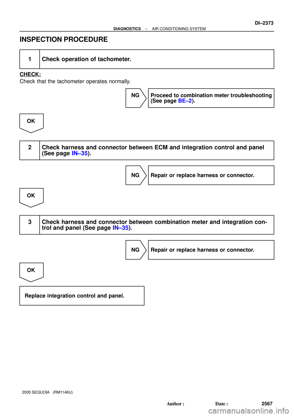
INSPECTION PROCEDURE
1 Check operation of tachometer.
CHECK:
Check that the tachometer operates normally.
NG Proceed to combination meter troubleshooting
(See page BE±2).
OK
2 Check harness and connector between ECM and integration control and panel
(See page IN±35).
NG Repair or replace harness or connector.
OK
3 Check harness and connector between combination meter and integration con-
trol and panel (See page IN±35).
NG Repair or replace harness or connector.
OK
Replace integration control and panel.
Page 2577 of 4323
I07839
21
± DIAGNOSTICSAIR CONDITIONING SYSTEM
DI±2375
2569 Author�: Date�:
2005 SEQUOIA (RM1146U)
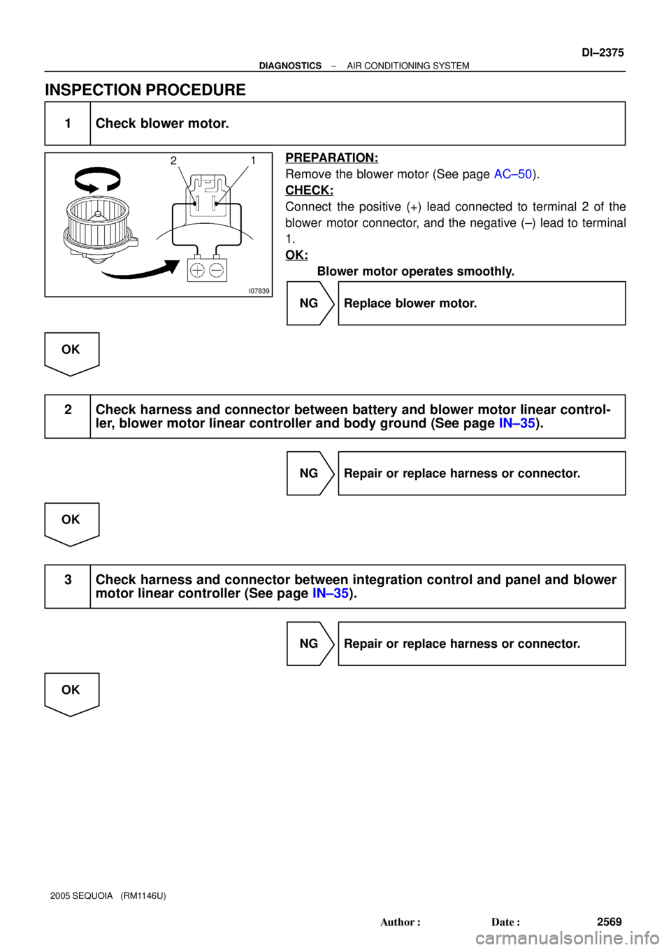
INSPECTION PROCEDURE
1 Check blower motor.
PREPARATION:
Remove the blower motor (See page AC±50).
CHECK:
Connect the positive (+) lead connected to terminal 2 of the
blower motor connector, and the negative (±) lead to terminal
1.
OK:
Blower motor operates smoothly.
NG Replace blower motor.
OK
2 Check harness and connector between battery and blower motor linear control-
ler, blower motor linear controller and body ground (See page IN±35).
NG Repair or replace harness or connector.
OK
3 Check harness and connector between integration control and panel and blower
motor linear controller (See page IN±35).
NG Repair or replace harness or connector.
OK
Page 2578 of 4323
DI±2376
± DIAGNOSTICSAIR CONDITIONING SYSTEM
2570 Author�: Date�:
2005 SEQUOIA (RM1146U)
4 Check integration control and panel (See page IN±35).
NG Replace integration control and panel.
OK
Replace blower motor linear controller.
Page 2581 of 4323
I28847
RrVMI21 Integration Control and Panel:
± DIAGNOSTICSAIR CONDITIONING SYSTEM
DI±2379
2573 Author�: Date�:
2005 SEQUOIA (RM1146U)
3 Check voltage between terminal RrVM of integration control and panel and body
ground.
PREPARATION:
Remove the integration control and panel with connectors still
connected.
CHECK:
(a) Turn the ignition switch to ON.
(b) Operate the rear A/C blower motor.
(c) Measure the voltage between terminal RrVM of the in-
tegration control and panel and body ground, when the
blower switch is operated as shown in the table below.
OK:
Blower speedVoltage
LO7.2 V
ME4.2 V
HI0.5 V
OK Proceed to next circuit inspection shown in
problem symptoms table (See page DI±2304).
NG
Page 2582 of 4323
I07763
1
2
4
I07764
3
4
DI±2380
± DIAGNOSTICSAIR CONDITIONING SYSTEM
2574 Author�: Date�:
2005 SEQUOIA (RM1146U)
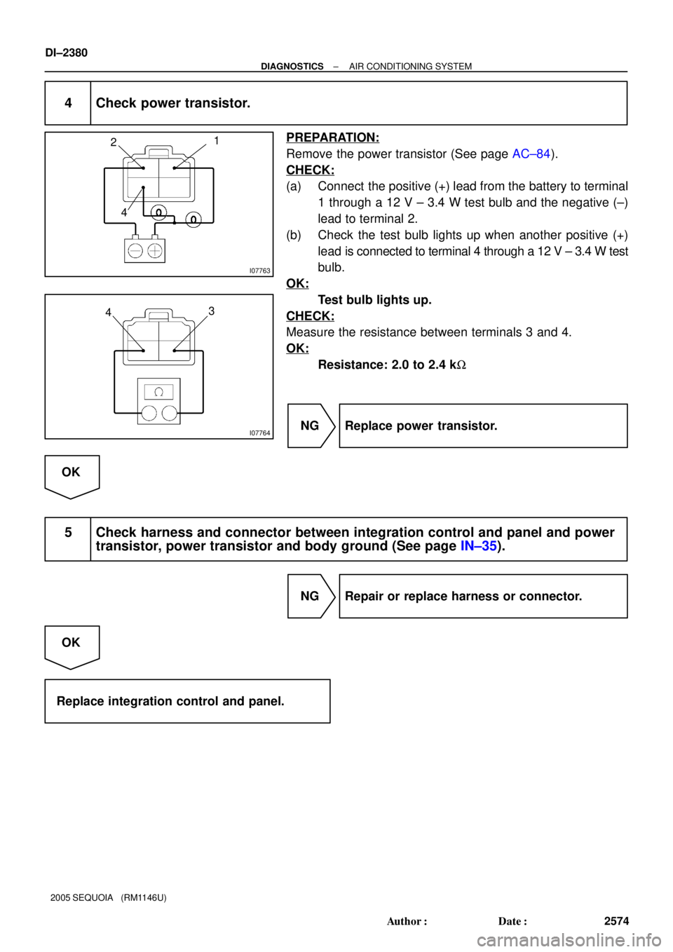
4 Check power transistor.
PREPARATION:
Remove the power transistor (See page AC±84).
CHECK:
(a) Connect the positive (+) lead from the battery to terminal
1 through a 12 V ± 3.4 W test bulb and the negative (±)
lead to terminal 2.
(b) Check the test bulb lights up when another positive (+)
lead is connected to terminal 4 through a 12 V ± 3.4 W test
bulb.
OK:
Test bulb lights up.
CHECK:
Measure the resistance between terminals 3 and 4.
OK:
Resistance: 2.0 to 2.4 kW
NG Replace power transistor.
OK
5 Check harness and connector between integration control and panel and power
transistor, power transistor and body ground (See page IN±35).
NG Repair or replace harness or connector.
OK
Replace integration control and panel.
Page 2584 of 4323

INSPECTION PROCEDURE
1 Read value of hand±held tester.
PREPARATION:
(a) Connect the hand±held tester to")
DI±2382
± DIAGNOSTICSAIR CONDITIONING SYSTEM
2576 Author�: Date�:
2005 SEQUOIA (RM1146U)
INSPECTION PROCEDURE
1 Read value of hand±held tester.
PREPARATION:
(a) Connect the hand±held tester to the DLC3.
(b) Turn the ignition switch ON and push the hand±held tester main SW ON.
CHECK:
Select the item below in the DATA LIST, and read the displays on the hand±held tester.
ENGINE AND ECT / ALL:
ItemMeasurement Item / Display
(Range)Normal ConditionDiagnostic Note
A/C SIGA/C signal / ON or OFF�A/C SW Pushed: ON
�A/C SW Released: OFF±
HINT:
Check with the engine running.
OK:
The display is as specified in the normal condition.
NG Go to step 8.
OK
2 Read value of hand±held tester.
PREPARATION:
(a) Connect the hand±held tester to the DLC3.
(b) Turn the ignition switch ON and push the hand±held tester main SW ON.
CHECK:
Select the item below in the DATA LIST, and read the displays on the hand±held tester.
ENGINE AND ECT / ALL:
ItemMeasurement Item / Display
(Range)Normal ConditionDiagnostic Note
A/C MAG CLUTCHA/C magnet clutch / ON or OFF�A/C SW ON: ON
�A/C SW OFF: OFF±
HINT:
Check with the engine running.
OK:
The display is as specified in the normal condition.
NG Replace ECM (See page SF±80).
OK